
 OpenMV MicroPython
 Quick Start#
Getting Started#
Please follow the steps below:
You will need the following two items to test the CMUcam4
A 4V to 9V DC external power supply capable of delivering at least 250 mA
This can be from an Arduino, FTDI Breakout Board, FTDI Cable, or Wall Wart
An NTSC TV (or compatible television monitor) and an RCA Cable
Setup to test the CMUcam4
Connect the NTSC TV to the CMUcam4’s RCA Coaxial Jack using the RCA Cable
Connect the external power supply to the CMUcam4’s DC Barrel Jack (or other power ports)
The green power LED should illuminate once you connect the external power supply to the CMUcam4. After about 2 seconds, the red auxiliary LED should illuminate to indicate the CMUcam4 is ready for action. If the green power LED does not illuminate please double check the external power supply connection.
Testing Procedure#
Please follow the steps below:
Press and hold the reset button on the CMUcam4
Press and hold the user button on the CMUcam4
Release the reset button (do not release the user button)
Wait until the red auxiliary LED turns on (2 seconds)
Wait until the red auxiliary LED starts blinking at 10 Hz and then release the user button
The TV should turn on (you should see a splash screen displayed on the TV)
The CMUcam4 will now adjust to the lighting conditions for the next 5 seconds
Do not place the object you want to track in front of the CMUcam4 for the next 5 seconds
Wait until the red auxiliary LED stops blinking at 10 Hz
The CMUcam4 is now done adjusting to lighting conditions
The pan and tilt servo pins should output 1500 μs pulses at 50 Hz
Place the object you want to track in front of the CMUcam4 and press the user button
If the red auxiliary LED begins blinking at 10 Hz examine the OV9665 camera module connection
The OV9665 camera module may be damaged and most likely needs to be replaced
You should now see the tracked object (or similar) displayed on the TV.
The pan and tilt servos, if connected, will also try to drive the camera towards the tracked object
Please try this procedure with different objects in different environments to see what works the best
Download the testing guide in PDF form here.
Communication Tools#
You will need one of the following (or similar) USB to Serial Converters to communicate with the CMUcam4:
-
You will also need an external power supply capable of powering the CMUcam4
Please connect the FTDI 5V Breakout Board to the 6-pin connector on the CMUcam4
-
You will also need an external power supply capable of powering the CMUcam4
Please connect the FTDI 3.3V Breakout Board to the 6-pin connector on the CMUcam4
A Prop Clip
You will also need an external power supply capable of powering the CMUcam4
Please connect the Prop Clip to the 4-pin connector on the CMUcam4
A Prop Plug
You will also need an external power supply capable of powering the CMUcam4
Please connect the Prop Plug to the 4-pin connector on the CMUcam4
-
Recommended for 5V tolerant systems
Please connect the FTDI 5V Cable w/ 5V I/O to the 6-pin connector on the CMUcam4
-
Recommended for 3.3V tolerant systems
Please connect the FTDI 5V Cable w/ 3.3V I/O to the 6-pin connector on the CMUcam4
Recommended Serial Terminal Programs#
The Parallax Serial Terminal is a handy tool for communication with serial-based microcontrollers such as the Parallax Propeller chip. It is the recommended serial terminal to use to communicate with the camera board. The Parallax Serial Terminal (PST) is a stand-alone application less than 1 MB in size and does not require installation to use. PST is available for download from Parallax Inc. here. Follow the below steps to setup PST:
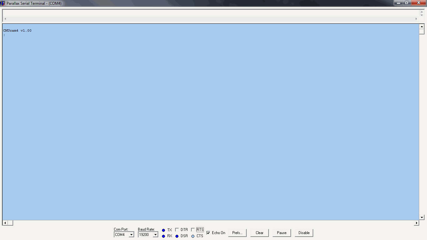
Run PST
Go to Echo On and make sure it is checked
Go to Com Port and select the COM port the CMUcam4 is connected to from the drop-down list
Go to Baud Rate and select 19200 from the drop-down list
Click Enable if necessary
For non-Windows users Brad’s SPIN Tool (BST) is recommended. BST can be downloaded here. BST is a graphical user interface (GUI) integrated development environment (IDE) stand-alone application less than 10 MB is size designed for the Parallax Propeller Chip and does not require installation to use. BST includes a built-in easy-to-use serial terminal. Follow the below steps to setup BST’s built-in easy-to-use serial terminal:
Run BST
Go to View and select Serial Terminal from the drop-down list
The bst Terminal should pop-up – please click on it
Go to Baud and select 19200 from the drop-down list
Go to Format and select 8 Bits and Parity None from the drop-down list
Go to Port and select the COM port the CMUcam4 is connected to from the drop-down list
Look for ports named /dev/tty/USB###
Go to Communicate and select Connect, Terminal Echo, and Reset Propeller from the drop-down menu
Go to Communicate and select Display ASCII for ASCII output or Display Hex for hex output
NOTE: You cannot use the FTDI 5V Cables with BST!
This is because BST pulls the green RTS wire low on the FTDI 5V Cable when you click Connect. This halts the CMUcam4 indefinitely. You can remove the green RTS wire from the connector to fix this problem.
Next Steps#
Your next steps (after taking a look at the Gallery) is to go to the documentation web page. Additionally, make sure to head over to our color-tracking explanation, tips and tricks, frequently asked questions, and Troubleshooting web pages for more information. Finally, head over to the Arduino Interface Library web page and take a look! Then you’re ready to build your own visual robots!