
 OpenMV MicroPython
 3.12. Reading analog with the ADC#
So far the camera has been reading digital signals – a pin is either 0 or 1, a switch is open or closed. Most signals that come off real-world sensors are analog: a continuous voltage that varies smoothly over some range. A photoresistor sweeps through every voltage between the rails as ambient brightness changes. A temperature sensor’s output drifts a few millivolts as a room heats up. A microphone’s output rises and falls with the sound around it.
An analog-to-digital converter (ADC) is the bridge. It samples the voltage on a pin and returns an integer that Python can read like any other value.
3.12.1. Quantization#
A digital value cannot represent a continuous voltage exactly. The ADC’s job is to quantize – snap each sample to the nearest of a fixed set of levels. An N-bit ADC has 2^N levels; a 12-bit converter has 4096 of them spread across its input range.
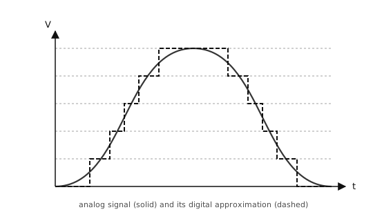
Quantization: each sample of the analog signal (solid) is rounded to one of a finite set of digital levels (stepped dashed line).#
The voltage between two adjacent levels is the step size of the ADC; anything smaller than that vanishes into rounding. A 12-bit ADC over a 3.3 V range has a step size of about 3.3 / 4096 ≈ 0.8 mV – fine enough that most signals look effectively continuous in software.
3.12.2. The machine.ADC class#
machine.ADC wraps one analog input channel. Construct it with the pin you want to read, then call read_u16():
from machine import ADC

adc = ADC("P6")
value = adc.read_u16()
print(value)
read_u16() always returns an unsigned 16-bit integer between 0 and 65535. The native ADC resolution varies by board (12-bit on STM32, port-specific elsewhere); the result is left-aligned into 16 bits so the hardware detail does not leak into Python – a value of 65535 is full-scale regardless of the chip.
The reference voltage – the input that corresponds to full-scale – depends on the board. Check the OpenMV Boards for the value on your cam. Anything above the reference reads as full-scale (and may damage the pin if it exceeds the absolute-maximum input voltage).
3.12.2.1. Converting counts to voltage#
The mapping from counts to voltage is linear, with full-scale counts mapping exactly to Vref:
voltage = counts × Vref / 65535
In code:
VREF = 3.3  # cam-dependent; see the quickref
counts = adc.read_u16()
voltage = counts * VREF / 65535
print(voltage, "V")
3.12.3. Voltage dividers#
Two resistors in series between a voltage rail and ground form a voltage divider. The node between them sits at a voltage set by the ratio of the two resistors:
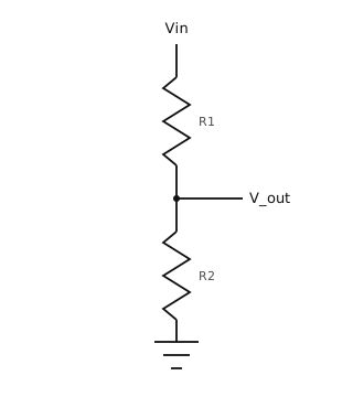
A voltage divider: R1 and R2 in series scale Vin down to V_out.#
V_out = Vin × R2 / (R1 + R2)
Equal resistors give half the rail voltage; R2 much smaller than R1 puts the tap close to ground; R2 much larger puts it close to the rail.
The formula assumes nothing else draws appreciable current from V_out. An ADC pin is high-impedance (megohms, nanoamps) and easily satisfies that, so a divider feeding an ADC behaves as the formula predicts.
3.12.4. Potentiometers#
A potentiometer is a single physical component that is exactly a voltage divider, with a sliding wiper that moves the tap between the two ends. Turning the knob changes R1 and R2 together while keeping their sum (the total resistance of the pot) constant.
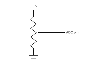
A potentiometer wired as a manual voltage source for the ADC: 3.3 V on one end, ground on the other, wiper to the pin.#
A pot is the canonical input device for trying out the ADC. Wire one end to 3.3 V, the other to ground, and the wiper to an ADC-capable pin; turning the knob sweeps the wiper through every voltage between the rails.
import time
from machine import ADC

pot = ADC("P6")
VREF = 3.3

while True:
    counts = pot.read_u16()
    voltage = counts * VREF / 65535
    print(voltage, "V")
    time.sleep_ms(100)
3.12.5. Reading higher voltages with a divider#
A voltage above Vref will pin the ADC at full-scale and may damage the input if it exceeds the absolute-maximum rating. To read a higher source – a battery, a sensor output that ranges beyond Vref – scale it down with a fixed voltage divider before it reaches the pin:
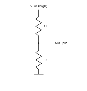
Scaling a high-voltage source to fit the ADC: R1 and R2 form a fixed voltage divider whose tap feeds the ADC pin.#
Pick R1 and R2 so the divided voltage stays inside the ADC’s range at the highest input voltage you expect:
V_adc = V_in × R2 / (R1 + R2)
For a maximum V_in = 12 V and a 3.3 V reference, the ratio R2 / (R1 + R2) must be at most 3.3 / 12 ≈ 0.275. A common pick with a little headroom is R1 = 33 kΩ, R2 = 10 kΩ. The ratio is 10 / 43 ≈ 0.233, so V_adc tops out at about 12 × 0.233 ≈ 2.79 V – safely below Vref.
To recover the original V_in from an ADC reading, invert the divider formula:
V_in = V_adc × (R1 + R2) / R2
In code:
from machine import ADC

R1 = 33_000
R2 = 10_000
VREF = 3.3

adc = ADC("P6")

counts = adc.read_u16()
v_adc = counts * VREF / 65535
v_in = v_adc * (R1 + R2) / R2
print(v_in, "V")
A few practical notes:
The divider draws
V_in / (R1 + R2)continuously. WithR1 + R2 = 43 kΩandV_in = 12 V, that is about 280 µA – usually negligible, but if the source is battery-powered consider larger resistors (100 kΩ to 1 MΩ) to cut idle drain.Resistor tolerance (typically ±1 % or ±5 %) feeds directly into measurement accuracy. Two ±5 % resistors can give the recovered
V_ina worst-case error of roughly ±10 %.The divider’s source impedance combines with any stray capacitance to low-pass-filter the input. For fast-changing signals that matters; for a battery-voltage check it does not.