OpenMV Boards
OpenMV cameras and Arduino boards running OpenMV firmware. Each page has the full pinout, peripheral mapping, supported drivers, and board-specific notes.
OpenMV cameras
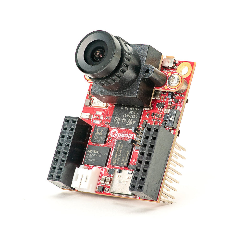
OpenMV N6 New
STM32N6 with built-in NPU — STMicro's first AI-accelerated MCU.
Explore →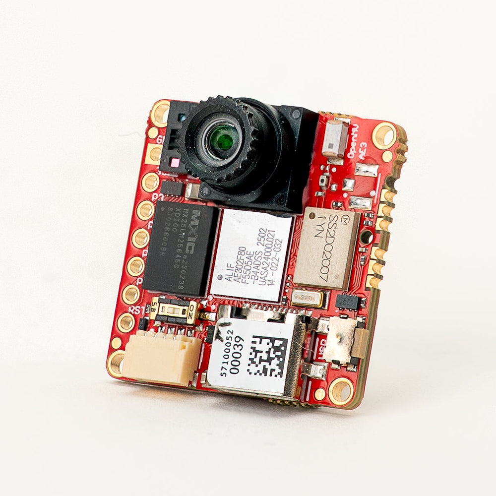
OpenMV AE3 New
Alif Ensemble E3 — fusion-class Cortex-M55 with Ethos-U55 NPU.
Explore →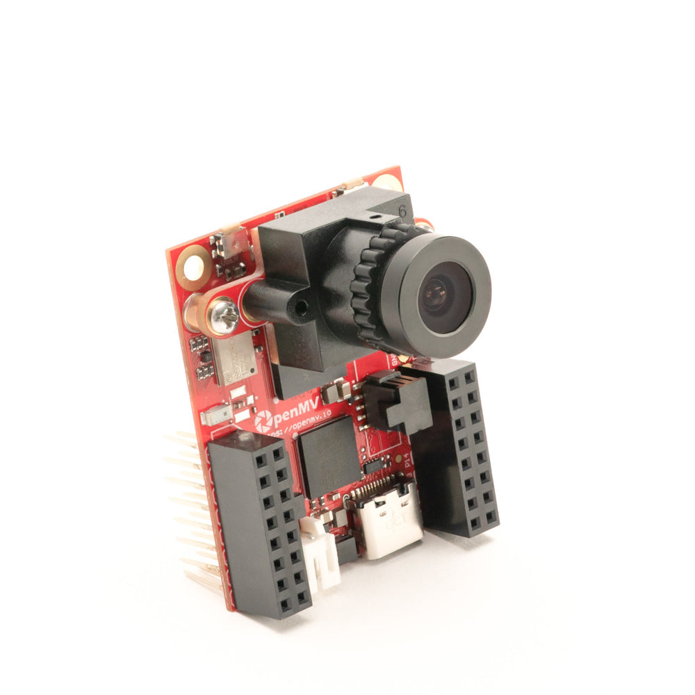
OpenMV RT1062
NXP i.MX RT1062 Cortex-M7 at 600 MHz with 32 MB external SDRAM.
Explore →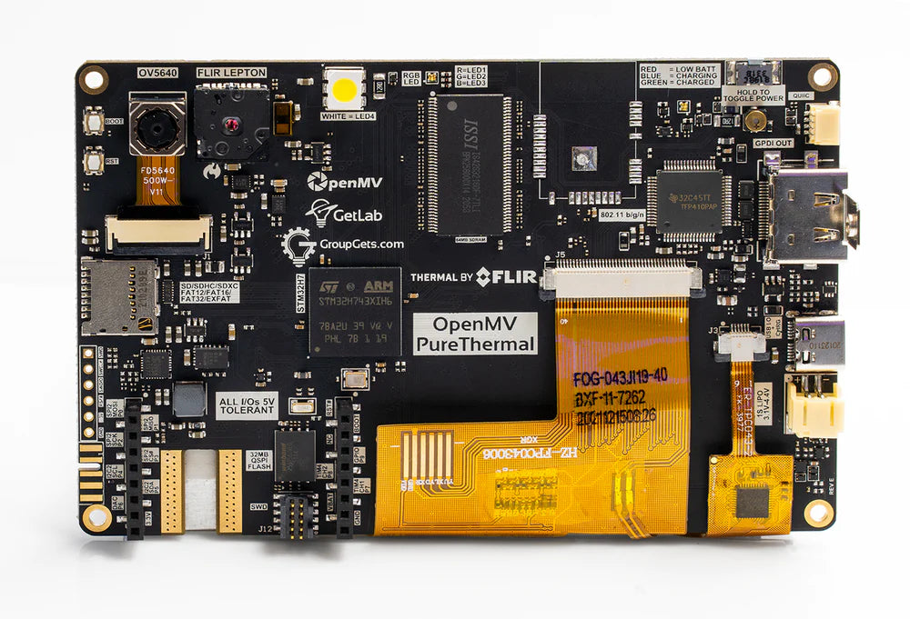
Pure Thermal
Dual color and thermal imaging plus DVI/HDMI output and a built-in touch LCD, STM32H7 host.
Explore →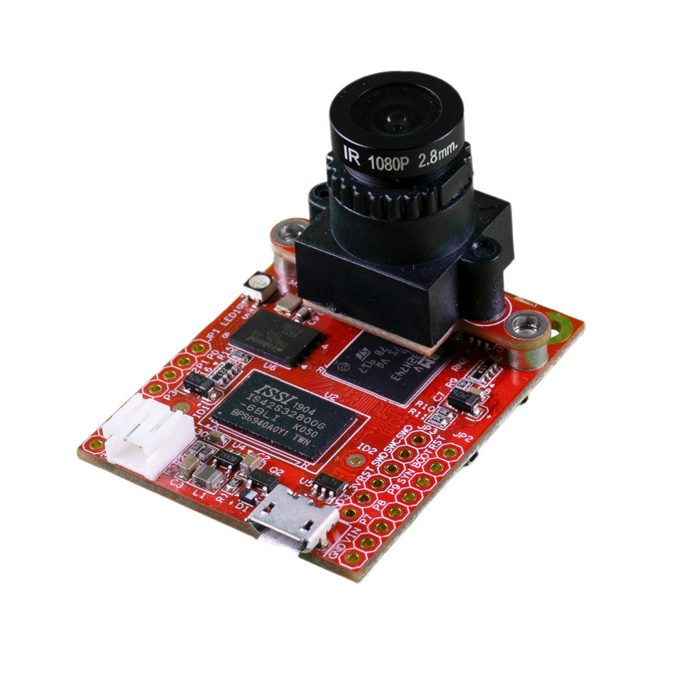
OpenMV H7 Plus
STM32H743 with 32 MB external SDRAM and a 5MP OV5640 sensor.
Explore →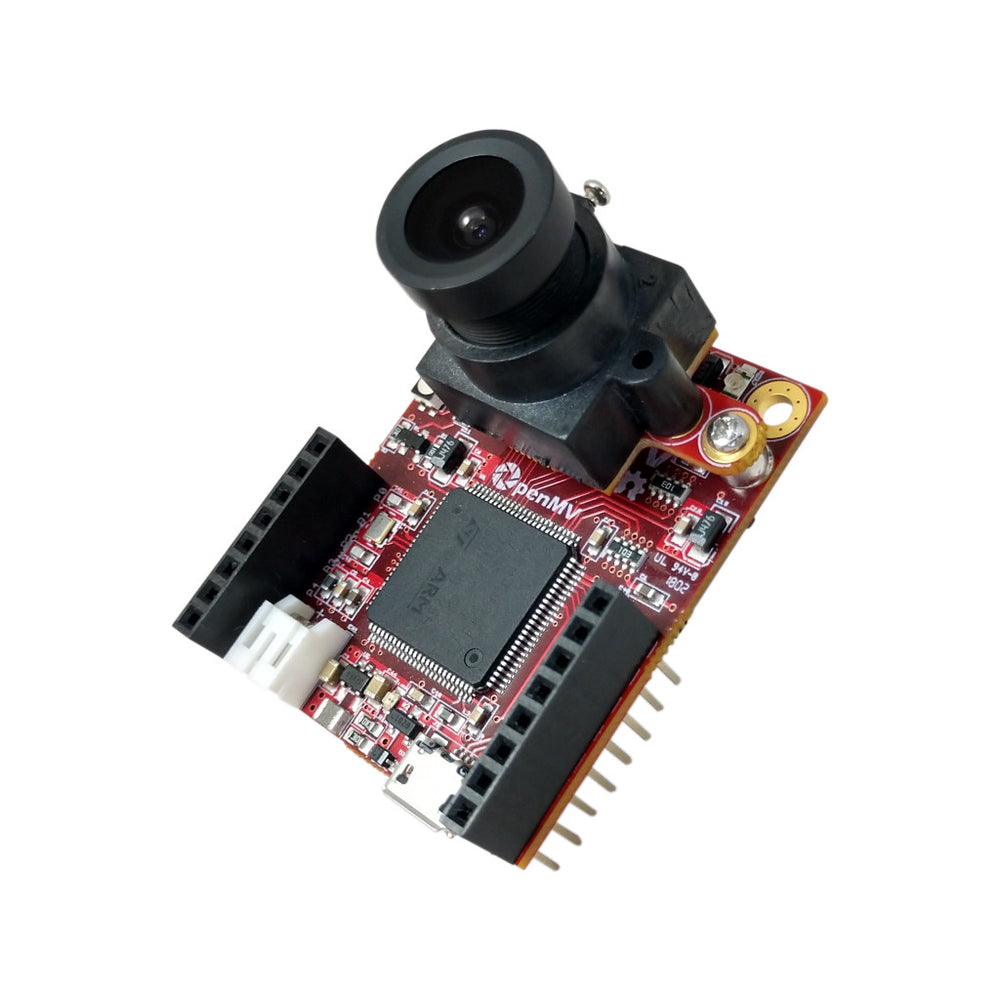
OpenMV H7
STM32H743 Cortex-M7 with a removable image sensor module.
Explore →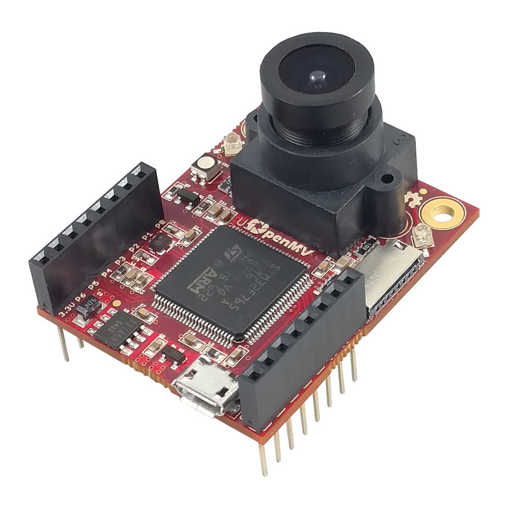
OpenMV M7 Legacy
STM32F765 Cortex-M7 — successor to the M4 with more memory and speed.
Explore →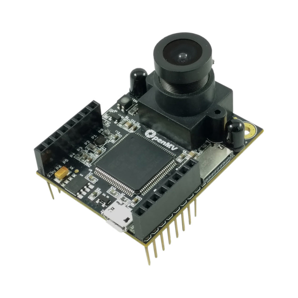
OpenMV M4 Legacy
STM32F427 Cortex-M4 — the first OpenMV Cam.
Explore →Arduino boards
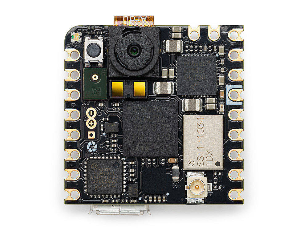
Arduino Nicla Vision
Compact 23 × 23 mm STM32H747 board with on-board sensor.
Explore →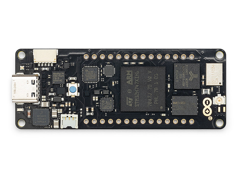
Arduino Portenta
STM32H747 with 8 MB SDRAM and Vision Shield support.
Explore →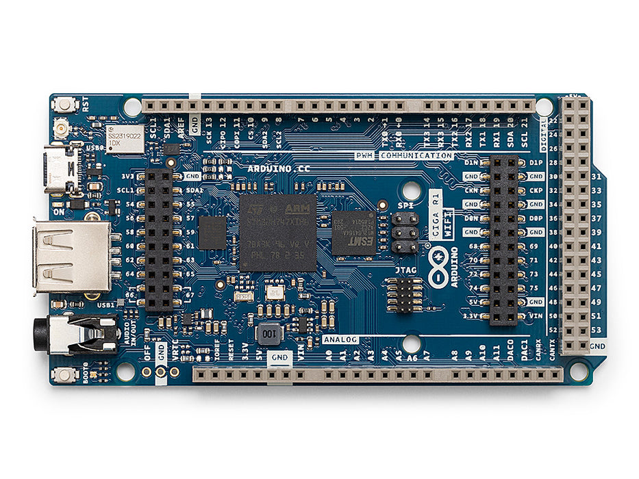
Arduino Giga
STM32H747 with 8 MB SDRAM, Vision and Display Shield support.
Explore →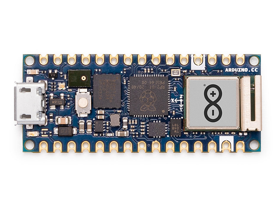
Arduino Nano RP2040 Connect Unsupported
RP2040 Cortex-M0+ with U-blox NINA Wi-Fi/BLE.
Explore →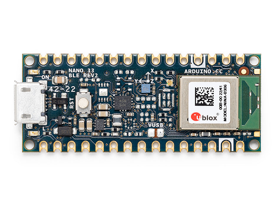
Arduino Nano 33 BLE Sense Unsupported
Nordic nRF52840 sensor board — no on-board image sensor.
Explore →