OpenMV AE3
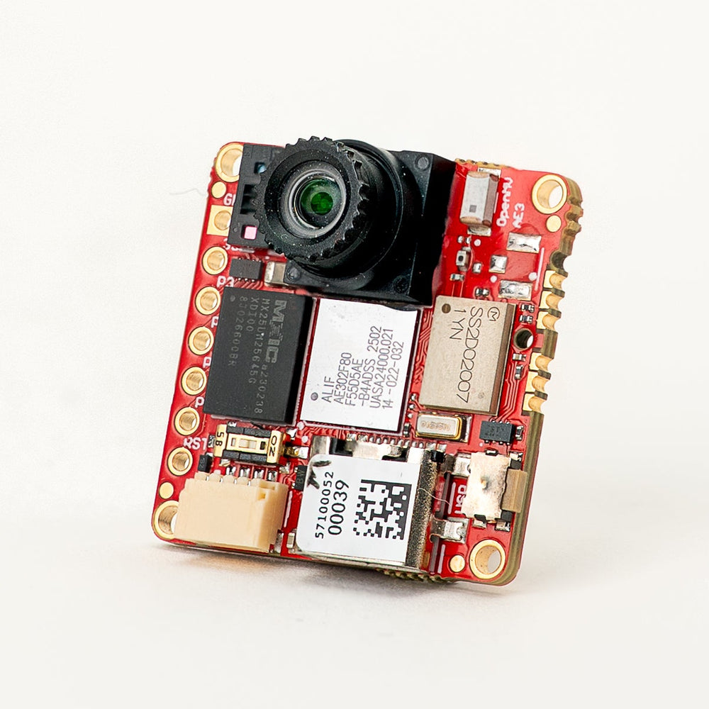
OpenMV AE3 围绕 Alif Ensemble E3 构建——这是一颗双核 ARM Cortex‑M55 SoC(400 MHz HP 核心 + 160 MHz HE 核心),片上集成两个 NPU(400 MHz / 204 GOPS HP NPU + 160 MHz / 46 GOPS HE NPU)。该开发板将这两个 NPU 与 PAG7936 1 MP 全局快门传感器、USB‑C 高速接口、Wi‑Fi、Bluetooth 5.1、一颗 LSM6DSM IMU、一个麦克风以及一颗 8×8 VL53L8CX 飞行时间测距仪相搭配,全部集成在一块 30 × 30 mm 的开发板上。
完整的数据手册、照片和尺寸信息请参见 OpenMV AE3 产品页面 。
亮点
Alif Ensemble E3 — 双核 ARM Cortex‑M55,配备 Helium 128‑bit SIMD,400 MHz HP 核心 + 160 MHz HE 核心(约 640 / 约 256 DMIPS,CoreMark 1748 / 752)。
双 NPU:400 MHz / 204 GOPS HP NPU + 160 MHz / 46 GOPS HE NPU,用于 AI/ML——可在运行其他工作负载的同时运行 YOLO 目标检测。
用于缩放的硬件 2D GPU。
13.5 MB 内部 SRAM,外加 5.5 MB 片上 MRAM 和 32 MB 外部八线闪存(100 MHz 8‑bit DDR,读取速度 200 MB/s)。
4 KB 备份 RAM,配合片上 RTC。
PAG7936 1 MP 彩色全局快门传感器。
板载 IMU(LSM6DSM 加速度计 + 陀螺仪)、麦克风,以及 VL53L8CX 8×8 飞行时间传感器(最远 4 m)。
高速 USB‑C(480 Mb/s),带 EMI 滤波和 TVS 保护,Wi‑Fi a/b/g/n + Bluetooth 5.1(芯片天线或 U.FL 选项)。
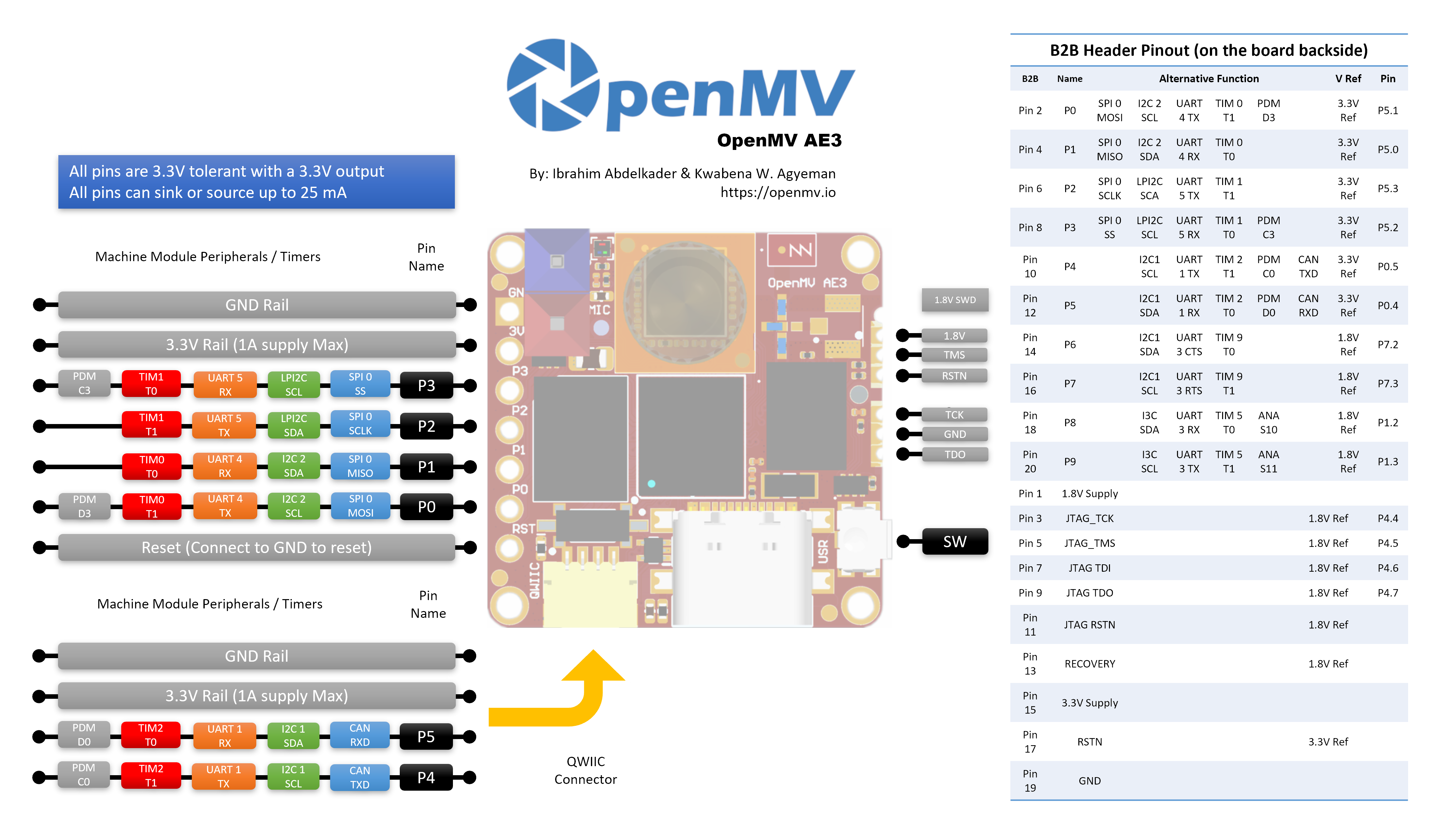
10 个用户 I/O 引脚 — P0–P3 位于侧边排针上,P4–P5 位于 Qwiic 接口上,P6–P9 位于背面的 B2B 排针上。额外的调试和恢复线也引出到 B2B 排针上。
所有引脚均为 3.3 V 输出 / 3.3 V 耐受,每个引脚 25 mA,支持中断。ADC 输入以 1.8 V 为基准。
用户 RGB LED、用户按钮、恢复开关、Qwiic 接口。
3.3 V 下 80 µA 深度睡眠(24 mA 空闲,50–60 mA 活动)。
警告
AE3 的 I/O 引脚 不耐受 5 V。不要将该设备直接连接到 Arduino Mega 之类的 5 V MCU——任何 5 V 信号都需要使用电平转换器。
引脚分布
引脚参考
AE3 在侧边排针上引出了 10 个用户引脚(P0–P9)。额外的信号——包括 JTAG 和恢复线——引出到开发板背面的 B2B(板对板)排针上,供扩展板和载板使用。
引脚名称 |
基准 |
功能 |
|---|---|---|
P0 |
3.3 V |
SPI0 MOSI / I2C2 SCL / UART4 TX / TIM0 T1 / PDM D3 |
P1 |
3.3 V |
SPI0 MISO / I2C2 SDA / UART4 RX / TIM0 T0 |
P2 |
3.3 V |
SPI0 SCLK / LPI2C SDA / UART5 TX / TIM1 T1 |
P3 |
3.3 V |
SPI0 SS / LPI2C SCL / UART5 RX / TIM1 T0 / PDM C3 |
P4 |
3.3 V |
I2C1 SCL / UART1 TX / TIM2 T1 / PDM C0 / CAN TX |
P5 |
3.3 V |
I2C1 SDA / UART1 RX / TIM2 T0 / PDM D0 / CAN RX |
P6 |
1.8 V |
I2C1 SDA / UART3 CTS / TIM9 T0 (B2B only) |
P7 |
1.8 V |
I2C1 SCL / UART3 RTS / TIM9 T1 (B2B only) |
P8 |
1.8 V |
I3C SDA / UART3 RX / TIM5 T0 / ADC ch S10 (B2B only) |
P9 |
1.8 V |
I3C SCL / UART3 TX / TIM5 T1 / ADC ch S11 (B2B only) |
P10 |
1.8 V |
GPIO / JTAG TCK (B2B only) |
P11 |
1.8 V |
GPIO / JTAG TDO (B2B only) |
P13 |
1.8 V |
GPIO / JTAG TMS (B2B only) |
P14 |
1.8 V |
GPIO / JTAG TDI (B2B only) |
RESET |
3.3 V |
拉低至 GND 以复位开发板 |
SW |
3.3 V |
用户按钮(低电平有效) |
LED_RED |
3.3 V |
RGB LED 红色通道(低电平有效) |
LED_GREEN |
3.3 V |
RGB LED 绿色通道(低电平有效) |
LED_BLUE |
3.3 V |
RGB LED 蓝色通道(低电平有效) |
备注
P0–P5 位于侧边排针上(以 3.3 V 为基准);P6–P9 仅在开发板背面的 B2B 排针上引出,并以 1.8 V 为基准。 向以 1.8 V 为基准的引脚输入 3.3 V 会损坏 SoC——请确保连接到 B2B 排针的任何信号都为 1.8 V。
电源引脚
3.3V — AE3 的主电源轨。同一条 3.3 V 电源轨在 GPIO 排针焊盘、Qwiic 接口以及开发板背面的 B2B 排针上均有引出。
1.8V — 在 B2B 排针上引出,仅作为输出。可用它为 B2B 载板上的 1.8 V 逻辑外设供电;不要从开发板外部向其灌入电压。
GND — 公共地。
AE3 没有 VIN 引脚,也没有 LiPo 充电器。它可以通过以下三种途径之一供电:
USB‑C — 板载稳压器将 USB 的 5 V 降至 3.3 V,并注入到 3.3 V 电源轨上。
Qwiic 接口 — 将一路稳压的 3.3 V 电源接入 Qwiic 排针,即可通过 Qwiic 模块为开发板供电。
GPIO 排针 / B2B 3.3 V 焊盘 — 将一路稳压的 3.3 V 电源接入 I/O 排针或 B2B 接口上任意 3.3 V 焊盘。
USB 稳压器通过一个理想二极管为电源轨供电,因此 Qwiic / GPIO / B2B 侧的外部 3.3 V 电源即使在 USB 仍然连接时也能为开发板供电,而不会反向驱动 USB 稳压器。
小技巧
可使用 电池续航估算器 来推算在给定的活动 / 深度睡眠占空比下 AE3 用一块电池能运行多久。
恢复和调试引脚
RESET — 拉低至 GND 以复位开发板。松开后 SoC 即正常启动。
开发板的正面(摄像头一侧),位于左下角有一个恢复开关。启用后,它会强制将 AE3 的 SE UART 输出到 USB 上,以便 OpenMV IDE 重新刷写板载引导加载程序。也可以通过将 B2B 接口上的 RECOVERY 引脚拉低来远程触发同样的恢复模式。
AE3 同时支持 SWD 和完整的 JTAG 调试:
开发板侧边的 1.8 V SWD 排针用于 Tag-Connect ECV3-06-CTX 线缆,引出四路 SWD 信号(TCK / TMS / TDO / RSTN)以及 GND。
开发板背面的 B2B 排针引出了相同的调试引脚(P10 = TCK、P11 = TDO、P13 = TMS、P14 = TDI),外加系统 RSTN 和一路独立的 JTAG RSTN。这些引脚既可用于 SWD(TCK + TMS),也可用于完整 JTAG;JTAG RSTN 线仅在完整 JTAG 模式下才需要。
所有调试信号均以 1.8 V 为基准——连接前请确保你的调试适配器已配置为 1.8 V 逻辑。
板载外设
LED
AE3 配有一颗用户 RGB LED,可通过 machine.LED 用软件控制:
from machine import LED

LED("LED_RED").on()
LED("LED_GREEN").on()
LED("LED_BLUE").on()
摄像头传感器
PAG7936 通过 csi --- 摄像头传感器 模块驱动:
import csi

cam = csi.CSI()
cam.reset()
cam.pixformat(csi.RGB565)
cam.framesize(csi.HD)         # 1280×800
cam.snapshot(time=2000)       # let auto‑exposure settle

while True:
    img = cam.snapshot()
PAG7936 支持触发模式——像素积分会与每一次 csi.CSI.snapshot 调用精确对齐,而非自由运行的帧时钟,这对将采集与外部事件或另一个传感器同步很有用。通过 csi.CSI.ioctl 配合 csi.IOCTL_SET_TRIGGERED_MODE 启用它。由于读出不再与下一帧的积分流水线化,帧率会降至自由运行模式的大约一半:
cam.ioctl(csi.IOCTL_SET_TRIGGERED_MODE, True)
NPU
AE3 的两个片上 NPU(400 MHz / 204 GOPS HP NPU + 160 MHz / 46 GOPS HE NPU)通过 ml --- 机器学习 模块对外暴露。存储在只读 /rom 文件系统上的模型可直接从闪存加载,无需复制到 RAM,因此即使是大型检测器也能与实时帧缓冲区舒适地共存。可在每一帧上运行一个 YOLOv8 检测器,并将预测结果绘制在实时图像之上:
import csi
import time
import ml
from ml.postprocessing.ultralytics import YoloV8

# Initialize the sensor.
csi0 = csi.CSI()
csi0.reset()
csi0.pixformat(csi.RGB565)
csi0.framesize(csi.VGA)

# Load YOLO V8 model from ROM FS.
model = ml.Model("/rom/yolov8n_192.tflite", postprocess=YoloV8(threshold=0.4))
print(model)

# Visualization parameters.
n = len(model.labels)
model_class_colors = [
    (int(255 * i // n), int(255 * (n - i - 1) // n), 255)
    for i in range(n)
]

clock = time.clock()
while True:
    clock.tick()
    img = csi0.snapshot()

    # boxes is a list of list per class of ((x, y, w, h), score) tuples
    boxes = model.predict([img])

    # Draw bounding boxes around the detected objects
    for i, class_detections in enumerate(boxes):
        rects = [r for r, score in class_detections]
        labels = [model.labels[i] for j in range(len(rects))]
        colors = [model_class_colors[i] for j in range(len(rects))]
        ml.utils.draw_predictions(img, rects, labels, colors, format=None)

    print(clock.fps(), "fps")
HE 核心
AE3 在一颗 MCU 中封装了两个 Cortex‑M55 核心:运行主 MicroPython 实例、摄像头、HP NPU、USB 等的高性能(HP)核心;以及功耗低得多、启动到自身一个小型 MicroPython 实例的高能效(HE)核心。两个核心共享一条 Open-AMP / RPMsg 消息总线,因此 HP 核心可以把 Python 函数分发到 HE 核心、取回结果,并让两半保持解耦。
最简单的入口是 @openamp.async_remote 装饰器。它会序列化一个 Python 函数、将其发送到 HE 核心,然后 HE 核心将其作为一个 asyncio 任务运行。注册任务后,用 HE 固件的闪存地址实例化 openamp.RemoteProc,并调用 rproc.start() 来启动第二个核心。在没有回调的情况下,被装饰函数的 print() 输出会通过默认端点转发到 HP 核心的标准输出——很适合做一个 “hello world”:
import time
import openamp

@openamp.async_remote
async def task1(ept):
    import asyncio
    while True:
        print("Hello from the HE core!")
        await asyncio.sleep(1)

# Boot the HE core. This runs the registered tasks.
rproc = openamp.RemoteProc(0x80320000)
rproc.start()

while True:
    print("Hello from the HP core!")
    time.sleep(1)
要实现双向消息传递,可向装饰器传入一个回调。每当 HE 任务调用 ept.send() 时,该回调就会在 HP 核心上运行:
import time
import openamp

def task_callback(src_addr, data):
    print("HP received:", data.decode())

@openamp.async_remote(task_callback)
async def task1(ept):
    import asyncio
    count = 0
    while True:
        ept.send(f"count = {count}")
        count += 1
        await asyncio.sleep(1)

rproc = openamp.RemoteProc(0x80320000)
rproc.start()

while True:
    time.sleep(1)
HE 核心拥有自己的 HE NPU(160 MHz,46 GOPS),因此它可以与 HP 核心的 HP NPU 正忙于的任务并行运行第二个 ML 模型。一种有用的分工方式是在 HE 一侧放一个小型的常开触发 / 分类器模型,仅在有有趣的内容被标记时才让 HP 核心做出反应——来自板载麦克风的关键词识别就很合适,因为它是连续的、低带宽的,而且 HE 核心的功耗远低于 HP。冻结的 ml.apps.MicroSpeech 辅助工具开箱即可识别 “Yes” 和 “No”——对着板载麦克风大声清晰地说出这些词即可触发检测:
import time
import openamp

def task_callback(src_addr, data):
    print("Heard:", data.decode())

@openamp.async_remote(task_callback)
async def task1(ept):
    from ml.apps import MicroSpeech
    speech = MicroSpeech(gain_db=24)
    while True:
        label, scores = speech.listen(timeout=0, threshold=0.70)
        if label:
            ept.send(label)

rproc = openamp.RemoteProc(0x80320000)
rproc.start()

while True:
    time.sleep(1)
若要实现更丰富的分工,可在 HP NPU 上运行 BlazeFace,同时让 HE 核心在后台处理关键词识别——HP 循环会把最近听到的关键词叠加显示在摄像头帧上:
import csi
import time
import openamp
import ml
from ml.postprocessing.mediapipe import BlazeFace

label = None
label_ticks = 0
LABEL_HOLD_MS = 2000

def task_callback(src_addr, data):
    global label, label_ticks
    label = data.decode()
    label_ticks = time.ticks_ms()

@openamp.async_remote(task_callback)
async def task1(ept):
    from ml.apps import MicroSpeech
    speech = MicroSpeech(gain_db=24)
    while True:
        l, scores = speech.listen(timeout=0, threshold=0.70)
        if l:
            ept.send(l)

# Start the HE core before initializing the camera on the HP core.
rproc = openamp.RemoteProc(0x80320000)
rproc.start()

csi0 = csi.CSI()
csi0.reset()
csi0.pixformat(csi.RGB565)
csi0.framesize(csi.VGA)
csi0.window((400, 400))

model = ml.Model("/rom/blazeface_front_128.tflite",
                 postprocess=BlazeFace(threshold=0.4))

clock = time.clock()
while True:
    clock.tick()
    img = csi0.snapshot()
    for r, score, keypoints in model.predict([img]):
        ml.utils.draw_predictions(img, [r], ("face",),
                                  ((0, 0, 255),), format=None)
        ml.utils.draw_keypoints(img, keypoints, color=(255, 0, 0))
    if label is not None:
        if time.ticks_diff(time.ticks_ms(), label_ticks) < LABEL_HOLD_MS:
            img.draw_string((4, 4), f"Heard: {label}",
                            color=(255, 0, 0), scale=2)
        else:
            label = None
    print(clock.fps(), "fps")
HE 核心非常适合你不希望与 HP 一侧的摄像头/NPU 流水线相互竞争的常开或低速率工作负载——小型 ML 推理、对麦克风或 IMU 数据的轻量级 DSP,以及类似的后台作业。
需要记住几条约束:
从 HE 核心驱动外设时,请限于麦克风和 IMU——这些正是 HE 一侧的设计用途。每个外设一次只能由一个核心拥有,因此请为它选定 HP 或 HE,并在脚本的整个生命周期内坚持这一选择。
每个
@openamp.async_remote任务体序列化后必须小于 500 字节的 mpy 字节码——请保持函数小巧,并把较重的逻辑拆分到单独的库模块中,这些模块会被冻结进固件。被分发函数内部的导入只能看到 HE 核心文件系统上存在的模块。HE 核心拥有自己的
/romROMFS——与 HP 核心的/rom相互独立——因此你希望在 HE 上可用的模块和 ML 模型需要烘焙进 HE 一侧的 ROMFS 映像,而不是 HP 那个。
麦克风
板载麦克风通过 audio --- 音频模块 采集。每个缓冲区以有符号 16 位 PCM bytearray 形式到达,这使得将其送入 ulab/numpy 做快速 DSP 变得轻而易举。一个简单的响度检测器——每当 RMS 音量越过阈值时打印:
import audio
from ulab import numpy as np

def loudness(pcmbuf):
    samples = np.array(np.frombuffer(pcmbuf, dtype=np.int16), dtype=np.float)
    rms = np.sqrt(np.mean(samples ** 2))
    if rms > 10000:
        print("Loud!", int(rms))

audio.init(channels=1, frequency=16000, gain_db=24)
audio.start_streaming(loudness)

while True:
    pass
IMU
板载 LSM6DSM 加速度计 + 陀螺仪通过 imu --- imu 传感器 对外暴露:
import imu
import time

while True:
    print(imu.acceleration_mg())   # (x, y, z) in milli‑g
    print(imu.angular_rate_mdps()) # (x, y, z) in milli‑deg/s
    time.sleep_ms(100)
飞行时间传感器
AE3 搭载一颗 VL53L8CX 8×8 多区域飞行时间传感器,每帧最多返回 64 个距离读数,最大量程约 4 m。它通过 tof --- 飞行时间传感器驱动 模块对外暴露——调用 tof.init() 启动传感器,调用 tof.read_depth() 以一个扁平的毫米读数列表(每个区域一个)形式抓取一个深度帧:
import tof

tof.init()
while True:
    depth, depth_min, depth_max = tof.read_depth()
    print("min:", depth_min, "mm  max:", depth_max, "mm")
深度数组也可以绘制到来自主传感器的彩色帧之上—— tof.draw_depth() 会将其绘制到一个已有的 image.Image 上,而 tof.snapshot() 则返回一张全新渲染的深度图像:
import image
import tof
import csi

# Bring up the VL53L8CX time-of-flight sensor.
tof.init()

# Configure the main camera at VGA RGB565.
cam = csi.CSI()
cam.reset()
cam.pixformat(csi.RGB565)
cam.framesize(csi.VGA)

# Off-screen framebuffer used to compose the camera frame and the
# up-scaled depth heat-map side by side before pushing the result
# back to the live preview.
b = image.Image(640, 480, image.RGB565)

while True:
    # Grab a colour frame from the main camera.
    img = cam.snapshot()

    try:
        # Capture TOF data [depth map, min distance, max distance].
        # vflip / hmirror align the ToF orientation with the camera.
        depth, dmin, dmax = tof.read_depth(vflip=True, hmirror=True)

        # Zones with no return read back as 0.0 — clamp them to the
        # frame's max distance so the colour palette doesn't show
        # them as "closest".
        for i in range(0, len(depth)):
            if depth[i] == 0.0:
                depth[i] = dmax

    except RuntimeError:
        # The sensor occasionally faults on a frame; reset and skip.
        tof.reset()
        continue

    # Draw the camera frame into the left half of the framebuffer,
    # scaled to 60% so it leaves room for the depth heat-map on
    # the right.
    b.draw_image(img, x=0, y=64+8, x_scale=0.6, hint=image.BILINEAR)

    # Up-sample the 8x8 depth array 30x with bicubic smoothing and
    # blend it into the right half using the depth palette.
    # scale=(0, 400) maps 0-400 mm to the full palette range.
    tof.draw_depth(b, depth, x=320+64+16, y=64+8, alpha=255,
                   hint=image.BICUBIC, x_scale=30, y_scale=30,
                   scale=(0, 400), color_palette=image.PALETTE_DEPTH)

    # Copy the composed framebuffer back into the live preview so
    # OpenMV IDE shows both panels.
    img.set(b)
Wi‑Fi
板载 CYW43439 通过 network --- 网络配置 以一个站点(station)接口对外暴露。连接后,ipconfig("addr4") 返回 (ip, netmask) 对:
import network, time

wlan = network.WLAN(network.STA_IF)
wlan.active(True)
wlan.connect("ssid", "password")
while not wlan.isconnected():
    time.sleep(1)
print("Wi‑Fi IP:", wlan.ipconfig("addr4")[0])
Bluetooth
同一颗 CYW43439 还提供 Bluetooth 5.1。可使用 aioble --- 异步 BLE 实现对 asyncio 友好的 BLE——例如,作为外设广播并等待中心设备连接:
import asyncio
import aioble

async def run():
    while True:
        conn = await aioble.advertise(250_000, name="OpenMV-AE3")
        print("Connected:", conn.device)
        await conn.disconnected()

asyncio.run(run())
总线参考
GPIO
使用 machine.Pin 来读取或驱动任意丝印引脚。输出为 3.3 V CMOS,每个引脚可灌入/拉出最多 25 mA。
from machine import Pin

out = Pin("P0", Pin.OUT)
out.on()
out.off()
out.value(1)

inp = Pin("P1", Pin.IN, Pin.PULL_UP)
print(inp.value())
任意输入引脚也可以在边沿跳变时触发中断:
def handler(pin):
    print("triggered:", pin)

Pin("P1", Pin.IN, Pin.PULL_UP).irq(
    handler, Pin.IRQ_FALLING | Pin.IRQ_RISING,
)
UART
总线 |
TX |
RX |
RTS |
CTS |
|---|---|---|---|---|
UART1 |
P4 |
P5 |
— |
— |
UART3 |
P9 |
P8 |
P7 |
P6 |
UART4 |
P0 |
P1 |
— |
— |
UART5 |
P2 |
P3 |
— |
— |
from machine import UART

uart = UART(1, baudrate=115200)
uart.write("hello")
uart.read(5)
UART3 是唯一带硬件流控的总线。由于 P6–P9 位于 B2B 排针上并以 1.8 V 为基准,UART3 只能通过电平转换器或 B2B 载板使用——不要直接给它接 3.3 V 逻辑。
I²C
总线 |
SCL |
SDA |
|---|---|---|
I2C1 |
P4 |
P5 |
I2C2 |
P0 |
P1 |
LPI2C |
P3 |
P2 |
from machine import I2C

i2c = I2C(1, freq=400_000)
i2c.scan()
i2c.writeto(0x76, b"hi")
板载 Qwiic 接口以 3.3 V 引出 I2C2。
I2C1 和 I2C2 还可以通过 machine.I2CTarget 在目标(从机)模式下使用,从而向另一个 I²C 控制器暴露一段内存区域:
from machine import I2CTarget

buf = bytearray(32)
target = I2CTarget(1, addr=0x42, mem=buf)
备注
LPI2C 外设未在固件中暴露。即使暴露,它也只能支持目标(从机)模式,而 I2C1 和 I2C2 已经涵盖了控制器和目标两种操作。
SPI
总线 |
MOSI |
MISO |
SCK |
CS |
|---|---|---|---|---|
SPI0 |
P0 |
P1 |
P2 |
P3 |
from machine import SPI
from machine import Pin

spi = SPI(0, baudrate=10_000_000)
cs = Pin("P3", Pin.OUT, value=1)   # CS is not driven by the SPI peripheral

cs.value(0)
spi.write(b"hello")
cs.value(1)
ADC
Alif Ensemble E3 在 P8 和 P9(仅 B2B 排针)上引出两路 12 位 ADC 通道。两路输入均以 1.8 V 为基准——read_u16 在引脚的 0–1.8 V 范围内返回 0–65535:
from machine import ADC
import time

adc = ADC("P8")
while True:
    voltage = adc.read_u16() * 1.8 / 65535
    print(voltage)
    time.sleep_ms(100)
警告
AE3 的 ADC 输入以 1.8 V 为基准,而非 3.3 V。直接灌入原始的 3.3 V 信号会使转换器饱和,并可能损坏引脚——请在外部将较高的电压分压降低。
PWM
引脚 |
定时器 / 通道 |
|---|---|
P0 |
TIM0 T1 |
P1 |
TIM0 T0 |
P2 |
TIM1 T1 |
P3 |
TIM1 T0 |
P4 |
TIM2 T1 |
P5 |
TIM2 T0 |
P6 |
TIM9 T0 (B2B only) |
P7 |
TIM9 T1 (B2B only) |
P8 |
TIM5 T0 (B2B only) |
P9 |
TIM5 T1 (B2B only) |
可通过 machine.PWM 驱动其中任意一个:
from machine import Pin, PWM

pwm = PWM(Pin("P0"), freq=1_000, duty_u16=32768)
软件位拍总线
如果你需要一条额外的总线,machine.SoftI2C 和 machine.SoftSPI 可在任意 GPIO 上工作。
热成像传感器(板外)
固件包含 fir --- 热成像传感器驱动(fir == 远红外) 驱动,用于外部接线的 AMG8833 8 × 8 热成像仪。将该模块连接到下面列出的 I²C 总线,然后用 fir.init() + fir.snapshot() 读取帧:
import time
import image
import fir

fir.init()                          # auto‑detects the sensor
clock = time.clock()

while True:
    clock.tick()
    try:
        img = fir.snapshot(x_scale=5, y_scale=5,
                           color_palette=image.PALETTE_IRONBOW,
                           hint=image.BICUBIC,
                           copy_to_fb=True)
    except OSError:
        continue
    print(clock.fps())
fir 驱动只通过 I²C 1 与传感器通信——请将模块接到 P4(SCL)和 P5(SDA)。
定时
time
time 模块涵盖阻塞延时、单调计时和经过时间测量:
import time

time.sleep(1)              # seconds
time.sleep_ms(500)
time.sleep_us(10)

start = time.ticks_ms()
# ...do work...
elapsed = time.ticks_diff(time.ticks_ms(), start)
虚拟定时器
machine.Timer 可调度周期性或单次回调,而不占用硬件定时器槽位。将 -1 作为 id 传入即可使用虚拟(软件)定时器:
from machine import Timer

one_shot = Timer(-1)
one_shot.init(period=5_000, mode=Timer.ONE_SHOT,
              callback=lambda t: print("once"))

periodic = Timer(-1)
periodic.init(period=2_000, mode=Timer.PERIODIC,
              callback=lambda t: print("tick"))
周期值以毫秒为单位。调用 deinit() 以停止并释放该槽位。
实时时钟
machine.RTC 在复位后仍保持挂钟时间,由片上 4 KB 备份 RAM 支持,可在深度睡眠中保持:
from machine import RTC

rtc = RTC()
rtc.datetime((2026, 4, 30, 4, 12, 0, 0, 0))   # Y, M, D, weekday, h, m, s, subsec
print(rtc.datetime())
RTC 在深度睡眠期间也会运行,因此你可以将它用作 machine.deepsleep() 的唤醒源。
启动与运行时信息
USB 引导加载程序窗口
每次上电时,摄像头都会运行一段短暂的引导加载程序(几秒钟),让 OpenMV IDE 无需用户进入 DFU 模式即可更新固件。该窗口结束后,引导加载程序会移交给 boot.py,然后是 main.py。
运行中的脚本可以通过调用 machine.bootloader() 按需重新进入引导加载程序:
import machine

machine.bootloader()
文件系统与启动顺序
AE3 固件在启动时最多挂载两个文件系统:
内部闪存 — 始终挂载在
/flash。默认保存main.py和README.txt;在首次启动时创建。ROMFS — 挂载在
/rom的只读、内存映射文件系统,用于存放受益于零拷贝访问的大型数据资源(例如 AI 模型)。在任何用户 Python 运行之前,由 MicroPython 在启动时自动挂载。
挂载完成后,工作目录被设为 /flash。解释器随后从该目录运行脚本:
boot.py在每一次软复位时执行(冷启动、在 REPL 中按Ctrl‑D,或运行中的脚本返回时)。main.py仅在冷启动时执行,紧接在boot.py之后。随后的软复位会重新运行boot.py,但会直接进入 REPL——要重新运行main.py,你必须完全复位开发板。
新刷写的开发板上随附的默认 main.py 只是把用户 RGB LED 的蓝色通道当作心跳闪烁(两次短脉冲,短间隔),这样你无需连接任何主机就能判断固件是否干净地启动了。
sys.path 被扩展以包含两个文件系统及其 lib/ 子目录,因此可导入的模块可以放在 /flash/lib 或 /rom/lib 中。
通过 USB 连接时,/flash 还会在主机上枚举为一个 USB 大容量存储驱动器,让你可以直接编辑 boot.py、main.py 以及任何其他文件。在复位摄像头之前请先弹出该驱动器,以便主机刷新其缓存的写入。
备注
由于操作系统将该驱动器视为被动块设备,在 OpenMV Cam 上运行的代码所创建或修改的文件,要等到主机重新挂载该驱动器后才会显示出来。如果操作系统和 OpenMV Cam 同时写入同一个文件系统,操作系统会胜出,并覆盖摄像头所做的更改。
备注
当主机正在从 USB 大容量存储驱动器读取或向其写入时,用户 RGB LED 的红色通道可能会短暂点亮——这是固件驱动的活动指示,而非故障。
存储容量
AE3 随附:
/flash— 8 MB FAT 文件系统,可读写。HP 核心上的
/rom— 24 MB 只读内存映射 ROMFS,用于 HP 核心在启动时加载的脚本和数据。HE 核心上的
/rom— 由 HE 核心拥有的 1 MB 只读 ROMFS。你希望@openamp.async_remote任务可用的模块和 ML 模型必须烘焙进这个映像,而不是 HP 那个。
硬错误指示
如果用户 RGB LED 正在快速循环所有颜色——快到看起来更像是一颗闪烁的白色 LED而非可分辨的各种色调——则说明固件遇到了不可恢复的硬错误。重新刷写固件即可恢复;如果重新刷写也无济于事,开发板可能已物理损坏。
软件库
完整的模块列表请参见 库索引——其中包括哪些模块是 AE3 构建所独有的。