OpenMV AE3
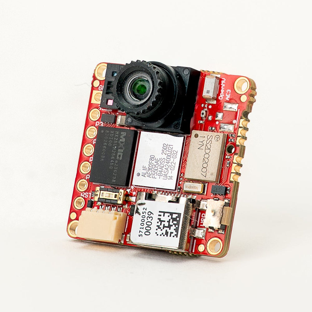
OpenMV AE3 以 Alif Ensemble E3 為核心打造——這是一款雙 ARM Cortex‑M55 SoC(400 MHz HP 核心 + 160 MHz HE 核心),內建兩顆 NPU(400 MHz / 204 GOPS HP NPU + 160 MHz / 46 GOPS HE NPU)。此開發板將這兩顆 NPU 與 PAG7936 1 MP 全域快門感測器、USB‑C 高速介面、Wi‑Fi、Bluetooth 5.1、LSM6DSM IMU、一顆麥克風,以及一顆 8×8 VL53L8CX 飛時測距儀整合在一塊 30 × 30 mm 的板子上。
完整的資料表、照片與尺寸請參閱 OpenMV AE3 產品頁面。
重點特色
Alif Ensemble E3 —— 雙 ARM Cortex‑M55,搭載 Helium 128 位元 SIMD,400 MHz HP 核心 + 160 MHz HE 核心(約 640 / 約 256 DMIPS,CoreMark 1748 / 752)。
雙 NPU:400 MHz / 204 GOPS HP NPU + 160 MHz / 46 GOPS HE NPU,用於 AI/ML——可在執行其他工作的同時運行 YOLO 物件偵測。
硬體 2D GPU,用於縮放。
13.5 MB 內部 SRAM,外加 5.5 MB 晶片內 MRAM 與 32 MB 外部八線快閃記憶體(100 MHz 8 位元 DDR,200 MB/s 讀取)。
4 KB 備份 RAM,搭配晶片內 RTC。
PAG7936 1 MP 彩色全域快門感測器。
板載 IMU(LSM6DSM 加速度計 + 陀螺儀)、麥克風,以及 VL53L8CX 8×8 飛時測距 感測器(最遠 4 m)。
高速 USB‑C(480 Mb/s),具備 EMI 濾波與 TVS 保護,Wi‑Fi a/b/g/n + Bluetooth 5.1(晶片天線或 U.FL 選項)。
10 個使用者 I/O 接腳 —— P0–P3 位於側邊排針,P4–P5 位於 Qwiic 連接器,P6–P9 位於背面的 B2B 排針。額外的除錯與復原線路同樣引出至 B2B 排針。
所有接腳皆為 3.3 V 輸出 / 3.3 V 容忍,每接腳 25 mA,支援中斷。ADC 輸入以 1.8 V 為參考電壓。
使用者 RGB LED、使用者按鈕、復原開關、Qwiic 連接器。
在 3.3 V 下 深度睡眠 80 µA(閒置 24 mA,運作 50–60 mA)。
警告
AE3 的 I/O 接腳 不可容忍 5 V。請勿將本裝置直接連接至如 Arduino Mega 等 5 V MCU——任何 5 V 訊號都請使用準位轉換器。
接腳圖
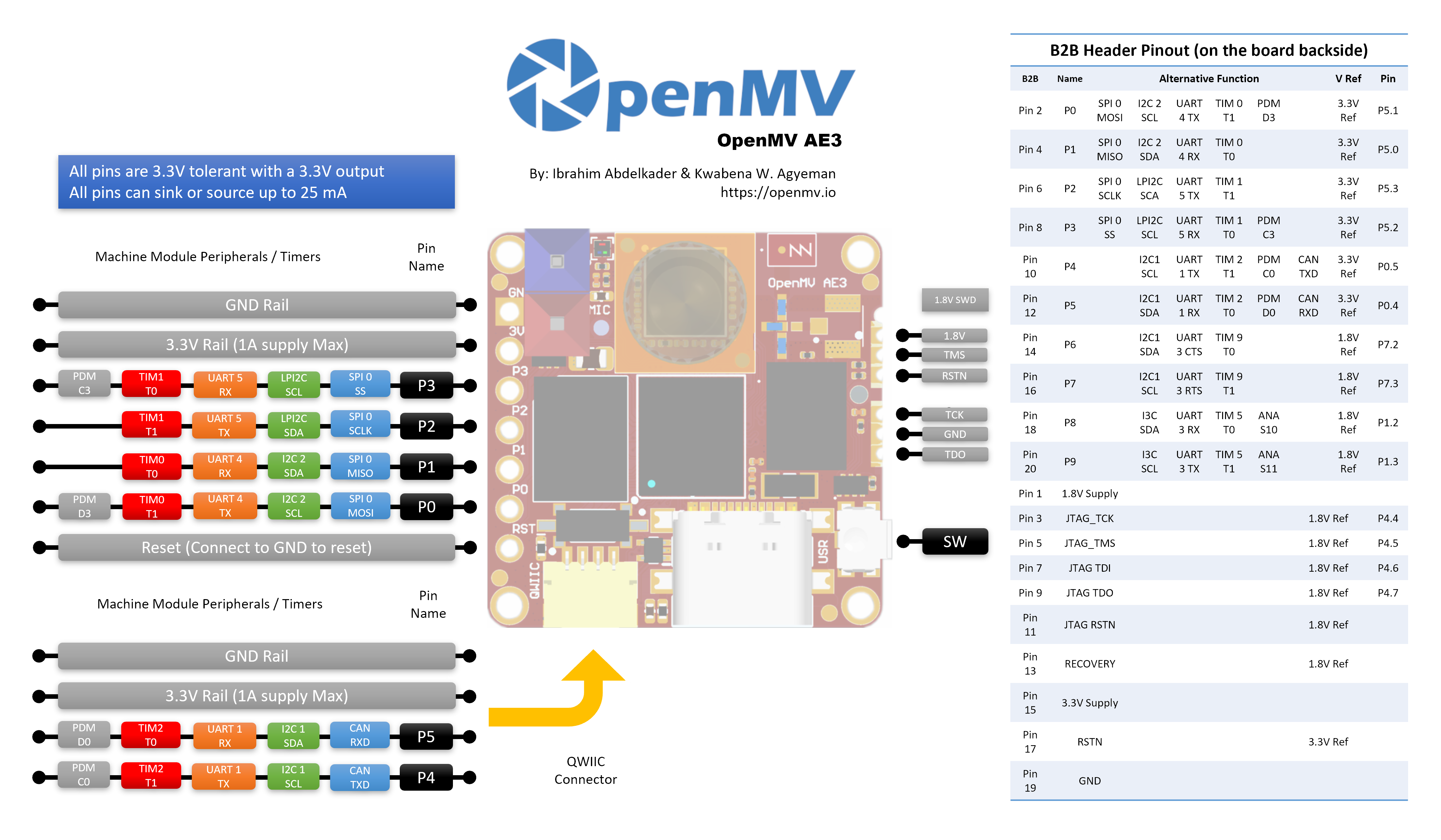
接腳參考
AE3 在側邊排針上引出 10 個使用者接腳(P0–P9)。額外訊號——包括 JTAG 與復原線路——則引出至板子 背面的 B2B(板對板)排針,供擴充板與載板使用。
接腳名稱 |
參考電壓 |
功能 |
|---|---|---|
P0 |
3.3 V |
SPI0 MOSI / I2C2 SCL / UART4 TX / TIM0 T1 / PDM D3 |
P1 |
3.3 V |
SPI0 MISO / I2C2 SDA / UART4 RX / TIM0 T0 |
P2 |
3.3 V |
SPI0 SCLK / LPI2C SDA / UART5 TX / TIM1 T1 |
P3 |
3.3 V |
SPI0 SS / LPI2C SCL / UART5 RX / TIM1 T0 / PDM C3 |
P4 |
3.3 V |
I2C1 SCL / UART1 TX / TIM2 T1 / PDM C0 / CAN TX |
P5 |
3.3 V |
I2C1 SDA / UART1 RX / TIM2 T0 / PDM D0 / CAN RX |
P6 |
1.8 V |
I2C1 SDA / UART3 CTS / TIM9 T0(僅 B2B) |
P7 |
1.8 V |
I2C1 SCL / UART3 RTS / TIM9 T1(僅 B2B) |
P8 |
1.8 V |
I3C SDA / UART3 RX / TIM5 T0 / ADC ch S10(僅 B2B) |
P9 |
1.8 V |
I3C SCL / UART3 TX / TIM5 T1 / ADC ch S11(僅 B2B) |
P10 |
1.8 V |
GPIO / JTAG TCK(僅 B2B) |
P11 |
1.8 V |
GPIO / JTAG TDO(僅 B2B) |
P13 |
1.8 V |
GPIO / JTAG TMS(僅 B2B) |
P14 |
1.8 V |
GPIO / JTAG TDI(僅 B2B) |
RESET |
3.3 V |
拉至 GND 以重置開發板 |
SW |
3.3 V |
使用者按鈕(低電位有效) |
LED_RED |
3.3 V |
RGB LED 紅色通道(低電位有效) |
LED_GREEN |
3.3 V |
RGB LED 綠色通道(低電位有效) |
LED_BLUE |
3.3 V |
RGB LED 藍色通道(低電位有效) |
備註
P0–P5 位於側邊排針(以 3.3 V 為參考);P6–P9 僅引出至板子背面的 B2B 排針,並以 1.8 V 為參考。 將 3.3 V 灌入以 1.8 V 為參考的接腳會損壞 SoC——請確保任何連接至 B2B 排針的訊號皆為 1.8 V。
電源接腳
3.3V —— AE3 的主要電源軌。同一條 3.3 V 電源軌引出至 GPIO 排針的焊接墊、Qwiic 連接器,以及板子背面的 B2B 排針。
1.8V —— 引出至 B2B 排針,僅作為輸出。可用來為 B2B 載板上的 1.8 V 邏輯周邊裝置供電;請勿從板外驅動此接腳。
GND —— 共用接地。
AE3 沒有 VIN 接腳,也沒有 LiPo 充電器。可透過以下三種途徑之一供電:
USB‑C —— 板載穩壓器將 USB 的 5 V 降至 3.3 V,並注入 3.3 V 電源軌。
Qwiic 連接器 —— 將穩壓後的 3.3 V 電源驅動至 Qwiic 排針,即可由 Qwiic 模組為開發板供電。
GPIO 排針 / B2B 3.3 V 焊接墊 —— 將穩壓後的 3.3 V 電源驅動至 I/O 排針或 B2B 連接器上任一 3.3 V 焊接墊。
USB 穩壓器透過 理想二極體 為電源軌供電,因此即使 USB 仍連接,Qwiic / GPIO / B2B 側的外部 3.3 V 電源也能為開發板供電,而不會反向驅動 USB 穩壓器。
小訣竅
請使用 電池續航估算器 來模擬 AE3 在給定的運作 / 深度睡眠工作週期下,以電池可運行多久。
復原與除錯接腳
RESET —— 拉至 GND 以重置開發板。釋放後 SoC 會正常啟動。
板子 正面(相機側)左下角 有一個 復原開關。啟用時會強制 AE3 的 SE UART 經由 USB 輸出,讓 OpenMV IDE 能重新燒錄板載開機載入程式。將 B2B 連接器上的 RECOVERY 接腳拉低,也能遠端觸發相同的復原模式。
AE3 同時支援 SWD 與完整的 JTAG 除錯:
板子側邊的 1.8 V SWD 排針 適用於 Tag-Connect ECV3-06-CTX 排線,引出四條 SWD 訊號(TCK / TMS / TDO / RSTN)外加 GND。
板子背面的 B2B 排針 引出相同的除錯接腳(P10 = TCK、P11 = TDO、P13 = TMS、P14 = TDI),外加系統 RSTN 與獨立的 JTAG RSTN。這些接腳可用於 SWD(TCK + TMS)或完整 JTAG;JTAG RSTN 線僅在完整 JTAG 模式下需要。
所有除錯訊號皆 以 1.8 V 為參考 —— 連接前請確保你的除錯轉接器已設定為 1.8 V 邏輯。
板載周邊裝置
LED
AE3 有一顆使用者 RGB LED,可透過 machine.LED 以軟體控制:
from machine import LED

LED("LED_RED").on()
LED("LED_GREEN").on()
LED("LED_BLUE").on()
相機感測器
PAG7936 透過 csi --- 相機感測器 模組驅動:
import csi

cam = csi.CSI()
cam.reset()
cam.pixformat(csi.RGB565)
cam.framesize(csi.HD)         # 1280×800
cam.snapshot(time=2000)       # let auto‑exposure settle

while True:
    img = cam.snapshot()
PAG7936 支援觸發模式——像素積分會與每次 csi.CSI.snapshot 呼叫精確對齊,而非依循自由運行的影格時脈,這對於將擷取與外部事件或另一顆感測器同步很有用。可透過 csi.CSI.ioctl 搭配 csi.IOCTL_SET_TRIGGERED_MODE 啟用。由於讀出不再與下一影格的積分流水線化處理,影格率會降至約自由運行模式的一半:
cam.ioctl(csi.IOCTL_SET_TRIGGERED_MODE, True)
NPU
AE3 的兩顆晶片內 NPU(400 MHz / 204 GOPS HP NPU + 160 MHz / 46 GOPS HE NPU)透過 ml --- 機器學習 模組存取。儲存在唯讀 /rom 檔案系統上的模型會直接從快閃記憶體載入,無需複製到 RAM,因此即使是大型偵測器也能與即時影格緩衝區一同舒適地運作。在每一影格上執行 YOLOv8 偵測器,並將預測結果繪製在即時影像之上:
import csi
import time
import ml
from ml.postprocessing.ultralytics import YoloV8

# Initialize the sensor.
csi0 = csi.CSI()
csi0.reset()
csi0.pixformat(csi.RGB565)
csi0.framesize(csi.VGA)

# Load YOLO V8 model from ROM FS.
model = ml.Model("/rom/yolov8n_192.tflite", postprocess=YoloV8(threshold=0.4))
print(model)

# Visualization parameters.
n = len(model.labels)
model_class_colors = [
    (int(255 * i // n), int(255 * (n - i - 1) // n), 255)
    for i in range(n)
]

clock = time.clock()
while True:
    clock.tick()
    img = csi0.snapshot()

    # boxes is a list of list per class of ((x, y, w, h), score) tuples
    boxes = model.predict([img])

    # Draw bounding boxes around the detected objects
    for i, class_detections in enumerate(boxes):
        rects = [r for r, score in class_detections]
        labels = [model.labels[i] for j in range(len(rects))]
        colors = [model_class_colors[i] for j in range(len(rects))]
        ml.utils.draw_predictions(img, rects, labels, colors, format=None)

    print(clock.fps(), "fps")
HE 核心
AE3 在單一 MCU 中封裝了兩顆 Cortex‑M55 核心:執行主 MicroPython 實例、相機、HP NPU、USB 等的 高效能(HP)核心;以及功耗低得多、自行啟動為一個小型 MicroPython 實例的 高效率(HE)核心。兩顆核心共用 Open-AMP / RPMsg 訊息匯流排,因此 HP 核心可將 Python 函式派發給 HE 核心、取回結果,並讓兩半保持解耦。
最簡單的入門方式是 @openamp.async_remote 裝飾器。它會封送一個 Python 函式、傳送至 HE 核心,HE 核心則將其作為 asyncio 工作執行。註冊工作後,以 HE 韌體的快閃記憶體位址實例化 openamp.RemoteProc,並呼叫 rproc.start() 來啟動第二顆核心。若不設回呼,被裝飾函式的 print() 輸出會透過預設端點轉送至 HP 核心的 stdout——非常適合寫「hello world」:
import time
import openamp

@openamp.async_remote
async def task1(ept):
    import asyncio
    while True:
        print("Hello from the HE core!")
        await asyncio.sleep(1)

# Boot the HE core. This runs the registered tasks.
rproc = openamp.RemoteProc(0x80320000)
rproc.start()

while True:
    print("Hello from the HP core!")
    time.sleep(1)
若要雙向傳訊,請將回呼傳給裝飾器。每當 HE 工作呼叫 ept.send() 時,該回呼便會在 HP 核心上執行:
import time
import openamp

def task_callback(src_addr, data):
    print("HP received:", data.decode())

@openamp.async_remote(task_callback)
async def task1(ept):
    import asyncio
    count = 0
    while True:
        ept.send(f"count = {count}")
        count += 1
        await asyncio.sleep(1)

rproc = openamp.RemoteProc(0x80320000)
rproc.start()

while True:
    time.sleep(1)
HE 核心擁有自己的 HE NPU(160 MHz,46 GOPS),因此可在 HP 核心的 HP NPU 忙於其他工作時,並行執行第二個 ML 模型。一個實用的分工方式是在 HE 側放置一個小型、常駐的觸發 / 分類模型,僅在偵測到有趣的事物時才讓 HP 核心做出反應——使用板載麥克風進行關鍵字辨識就很適合,因為它是連續、低頻寬的,且 HE 核心的功耗比 HP 低得多。凍結的 ml.apps.MicroSpeech 輔助工具開箱即可辨識「Yes」與「No」——對著板載麥克風大聲清楚地說出這些詞即可觸發偵測:
import time
import openamp

def task_callback(src_addr, data):
    print("Heard:", data.decode())

@openamp.async_remote(task_callback)
async def task1(ept):
    from ml.apps import MicroSpeech
    speech = MicroSpeech(gain_db=24)
    while True:
        label, scores = speech.listen(timeout=0, threshold=0.70)
        if label:
            ept.send(label)

rproc = openamp.RemoteProc(0x80320000)
rproc.start()

while True:
    time.sleep(1)
若要更豐富的分工,可在 HP NPU 上執行 BlazeFace,同時讓 HE 核心在背景處理關鍵字辨識——HP 迴圈會將最近聽到的關鍵字疊加在相機影格上:
import csi
import time
import openamp
import ml
from ml.postprocessing.mediapipe import BlazeFace

label = None
label_ticks = 0
LABEL_HOLD_MS = 2000

def task_callback(src_addr, data):
    global label, label_ticks
    label = data.decode()
    label_ticks = time.ticks_ms()

@openamp.async_remote(task_callback)
async def task1(ept):
    from ml.apps import MicroSpeech
    speech = MicroSpeech(gain_db=24)
    while True:
        l, scores = speech.listen(timeout=0, threshold=0.70)
        if l:
            ept.send(l)

# Start the HE core before initializing the camera on the HP core.
rproc = openamp.RemoteProc(0x80320000)
rproc.start()

csi0 = csi.CSI()
csi0.reset()
csi0.pixformat(csi.RGB565)
csi0.framesize(csi.VGA)
csi0.window((400, 400))

model = ml.Model("/rom/blazeface_front_128.tflite",
                 postprocess=BlazeFace(threshold=0.4))

clock = time.clock()
while True:
    clock.tick()
    img = csi0.snapshot()
    for r, score, keypoints in model.predict([img]):
        ml.utils.draw_predictions(img, [r], ("face",),
                                  ((0, 0, 255),), format=None)
        ml.utils.draw_keypoints(img, keypoints, color=(255, 0, 0))
    if label is not None:
        if time.ticks_diff(time.ticks_ms(), label_ticks) < LABEL_HOLD_MS:
            img.draw_string((4, 4), f"Heard: {label}",
                            color=(255, 0, 0), scale=2)
        else:
            label = None
    print(clock.fps(), "fps")
HE 核心非常適合處理你不希望與 HP 側相機/NPU 流水線競爭資源的常駐或低速率工作——小型 ML 推論、針對麥克風或 IMU 資料的輕量 DSP,以及類似的背景作業。
需牢記的幾項限制:
從 HE 核心驅動周邊裝置時,請限於麥克風與 IMU——這些正是 HE 側的設計用途。每個周邊裝置同一時間只能由一顆核心擁有,因此請為它挑選 HP 或 HE,並在指令碼的整個生命週期中沿用該選擇。
每個
@openamp.async_remote工作主體封送後必須小於 500 位元組的 mpy 位元組碼——請讓函式保持精簡,並將較重的邏輯拆分到凍結進韌體的獨立程式庫模組中。派發函式內部的 import 只能看到 HE 核心檔案系統上存在的模組。HE 核心有自己的
/romROMFS——與 HP 核心的/rom分開——因此你想在 HE 上使用的模組與 ML 模型,需要烘焙進 HE 側的 ROMFS 映像,而非 HP 側的。
麥克風
板載麥克風透過 audio --- 音訊模組 擷取。每個緩衝區以帶符號 16 位元 PCM bytearray 的形式抵達,這讓它能輕鬆餵入 ulab/numpy 做快速 DSP。一個簡單的響度偵測器——每當 RMS 音量越過閾值時就印出訊息:
import audio
from ulab import numpy as np

def loudness(pcmbuf):
    samples = np.array(np.frombuffer(pcmbuf, dtype=np.int16), dtype=np.float)
    rms = np.sqrt(np.mean(samples ** 2))
    if rms > 10000:
        print("Loud!", int(rms))

audio.init(channels=1, frequency=16000, gain_db=24)
audio.start_streaming(loudness)

while True:
    pass
IMU
板載 LSM6DSM 加速度計 + 陀螺儀透過 imu --- imu 感測器 存取:
import imu
import time

while True:
    print(imu.acceleration_mg())   # (x, y, z) in milli‑g
    print(imu.angular_rate_mdps()) # (x, y, z) in milli‑deg/s
    time.sleep_ms(100)
飛時測距感測器
AE3 搭載一顆 VL53L8CX 8×8 多區域飛時測距感測器,每影格可回傳多達 64 個距離讀數,最大量測範圍約 4 m。它透過 tof --- 飛時測距感測器驅動程式 模組存取——呼叫 tof.init() 啟動感測器,呼叫 tof.read_depth() 以平面化的毫米讀數清單(每區域一個)擷取一個深度影格:
import tof

tof.init()
while True:
    depth, depth_min, depth_max = tof.read_depth()
    print("min:", depth_min, "mm  max:", depth_max, "mm")
深度陣列也可繪製在主感測器的彩色影格之上—— tof.draw_depth() 會將其繪製到既有的 image.Image 上,而 tof.snapshot() 則回傳一張即時算繪的深度影像:
import image
import tof
import csi

# Bring up the VL53L8CX time-of-flight sensor.
tof.init()

# Configure the main camera at VGA RGB565.
cam = csi.CSI()
cam.reset()
cam.pixformat(csi.RGB565)
cam.framesize(csi.VGA)

# Off-screen framebuffer used to compose the camera frame and the
# up-scaled depth heat-map side by side before pushing the result
# back to the live preview.
b = image.Image(640, 480, image.RGB565)

while True:
    # Grab a colour frame from the main camera.
    img = cam.snapshot()

    try:
        # Capture TOF data [depth map, min distance, max distance].
        # vflip / hmirror align the ToF orientation with the camera.
        depth, dmin, dmax = tof.read_depth(vflip=True, hmirror=True)

        # Zones with no return read back as 0.0 — clamp them to the
        # frame's max distance so the colour palette doesn't show
        # them as "closest".
        for i in range(0, len(depth)):
            if depth[i] == 0.0:
                depth[i] = dmax

    except RuntimeError:
        # The sensor occasionally faults on a frame; reset and skip.
        tof.reset()
        continue

    # Draw the camera frame into the left half of the framebuffer,
    # scaled to 60% so it leaves room for the depth heat-map on
    # the right.
    b.draw_image(img, x=0, y=64+8, x_scale=0.6, hint=image.BILINEAR)

    # Up-sample the 8x8 depth array 30x with bicubic smoothing and
    # blend it into the right half using the depth palette.
    # scale=(0, 400) maps 0-400 mm to the full palette range.
    tof.draw_depth(b, depth, x=320+64+16, y=64+8, alpha=255,
                   hint=image.BICUBIC, x_scale=30, y_scale=30,
                   scale=(0, 400), color_palette=image.PALETTE_DEPTH)

    # Copy the composed framebuffer back into the live preview so
    # OpenMV IDE shows both panels.
    img.set(b)
Wi‑Fi
板載 CYW43439 透過 network --- 網路設定 以站台介面的形式存取。連線後,ipconfig("addr4") 會回傳 (ip, netmask) 配對:
import network, time

wlan = network.WLAN(network.STA_IF)
wlan.active(True)
wlan.connect("ssid", "password")
while not wlan.isconnected():
    time.sleep(1)
print("Wi‑Fi IP:", wlan.ipconfig("addr4")[0])
Bluetooth
同一顆 CYW43439 也提供 Bluetooth 5.1。請使用 aioble --- 非同步 BLE 進行對 asyncio 友善的 BLE——例如,以周邊裝置身分廣播並等待中央裝置連線:
import asyncio
import aioble

async def run():
    while True:
        conn = await aioble.advertise(250_000, name="OpenMV-AE3")
        print("Connected:", conn.device)
        await conn.disconnected()

asyncio.run(run())
匯流排參考
GPIO
使用 machine.Pin 來讀取或驅動任何絲印標示的接腳。輸出為 3.3 V CMOS,每接腳可吸入/輸出最高 25 mA。
from machine import Pin

out = Pin("P0", Pin.OUT)
out.on()
out.off()
out.value(1)

inp = Pin("P1", Pin.IN, Pin.PULL_UP)
print(inp.value())
任何輸入接腳也可在邊緣轉態時觸發中斷:
def handler(pin):
    print("triggered:", pin)

Pin("P1", Pin.IN, Pin.PULL_UP).irq(
    handler, Pin.IRQ_FALLING | Pin.IRQ_RISING,
)
UART
匯流排 |
TX |
RX |
RTS |
CTS |
|---|---|---|---|---|
UART1 |
P4 |
P5 |
— |
— |
UART3 |
P9 |
P8 |
P7 |
P6 |
UART4 |
P0 |
P1 |
— |
— |
UART5 |
P2 |
P3 |
— |
— |
from machine import UART

uart = UART(1, baudrate=115200)
uart.write("hello")
uart.read(5)
UART3 是唯一具備硬體流量控制的匯流排。由於 P6–P9 位於 B2B 排針上且 以 1.8 V 為參考,UART3 只能透過準位轉換器或 B2B 載板使用——請勿直接連接 3.3 V 邏輯。
I²C
匯流排 |
SCL |
SDA |
|---|---|---|
I2C1 |
P4 |
P5 |
I2C2 |
P0 |
P1 |
LPI2C |
P3 |
P2 |
from machine import I2C

i2c = I2C(1, freq=400_000)
i2c.scan()
i2c.writeto(0x76, b"hi")
板載 Qwiic 連接器以 3.3 V 引出 I2C2。
I2C1 與 I2C2 也可透過 machine.I2CTarget 以目標(從屬)模式使用,將一塊記憶體區域暴露給另一個 I²C 控制器:
from machine import I2CTarget

buf = bytearray(32)
target = I2CTarget(1, addr=0x42, mem=buf)
備註
LPI2C 周邊裝置未在韌體中提供。即使提供,它也只會支援 目標(從屬)模式,而 I2C1 與 I2C2 已涵蓋控制器與目標兩種操作。
SPI
匯流排 |
MOSI |
MISO |
SCK |
CS |
|---|---|---|---|---|
SPI0 |
P0 |
P1 |
P2 |
P3 |
from machine import SPI
from machine import Pin

spi = SPI(0, baudrate=10_000_000)
cs = Pin("P3", Pin.OUT, value=1)   # CS is not driven by the SPI peripheral

cs.value(0)
spi.write(b"hello")
cs.value(1)
ADC
Alif Ensemble E3 在 P8 與 P9(僅 B2B 排針)上提供兩個 12 位元 ADC 通道。兩個輸入皆 以 1.8 V 為參考——read_u16 在接腳處 0–1.8 V 的範圍內回傳 0–65535:
from machine import ADC
import time

adc = ADC("P8")
while True:
    voltage = adc.read_u16() * 1.8 / 65535
    print(voltage)
    time.sleep_ms(100)
警告
AE3 的 ADC 輸入 以 1.8 V 為參考,而非 3.3 V。直接灌入原始 3.3 V 訊號會使轉換器飽和,並可能損壞接腳——請在外部將較高電壓分壓降低。
PWM
接腳 |
計時器 / 通道 |
|---|---|
P0 |
TIM0 T1 |
P1 |
TIM0 T0 |
P2 |
TIM1 T1 |
P3 |
TIM1 T0 |
P4 |
TIM2 T1 |
P5 |
TIM2 T0 |
P6 |
TIM9 T0(僅 B2B) |
P7 |
TIM9 T1(僅 B2B) |
P8 |
TIM5 T0(僅 B2B) |
P9 |
TIM5 T1(僅 B2B) |
透過 machine.PWM 驅動其中任一個:
from machine import Pin, PWM

pwm = PWM(Pin("P0"), freq=1_000, duty_u16=32768)
軟體位元拍打匯流排
若你需要額外的匯流排,machine.SoftI2C 與 machine.SoftSPI 可在任何 GPIO 上運作。
熱感測器(板外)
韌體包含 fir --- 熱感測器驅動程式 (fir == far infrared,遠紅外線) 驅動程式,適用於外接的 AMG8833 8 × 8 熱成像器。將模組連接至下方列出的 I²C 匯流排,然後以 fir.init() + fir.snapshot() 讀取影格:
import time
import image
import fir

fir.init()                          # auto‑detects the sensor
clock = time.clock()

while True:
    clock.tick()
    try:
        img = fir.snapshot(x_scale=5, y_scale=5,
                           color_palette=image.PALETTE_IRONBOW,
                           hint=image.BICUBIC,
                           copy_to_fb=True)
    except OSError:
        continue
    print(clock.fps())
fir 驅動程式只能透過 I²C 1 與感測器通訊——請將模組接到 P4(SCL)與 P5(SDA)。
計時
time
time 模組涵蓋阻塞式延遲、單調節拍,以及經過時間量測:
import time

time.sleep(1)              # seconds
time.sleep_ms(500)
time.sleep_us(10)

start = time.ticks_ms()
# ...do work...
elapsed = time.ticks_diff(time.ticks_ms(), start)
虛擬計時器
machine.Timer 可排程週期性或單次回呼,而不佔用硬體計時器插槽。將 -1 作為 id 傳入即可使用虛擬(軟體)計時器:
from machine import Timer

one_shot = Timer(-1)
one_shot.init(period=5_000, mode=Timer.ONE_SHOT,
              callback=lambda t: print("once"))

periodic = Timer(-1)
periodic.init(period=2_000, mode=Timer.PERIODIC,
              callback=lambda t: print("tick"))
週期值的單位為毫秒。呼叫 deinit() 以停止並釋放插槽。
即時時鐘
machine.RTC 可在多次重置之間保持實際時鐘時間,由能撐過深度睡眠的 4 KB 晶片內備份 RAM 支援:
from machine import RTC

rtc = RTC()
rtc.datetime((2026, 4, 30, 4, 12, 0, 0, 0))   # Y, M, D, weekday, h, m, s, subsec
print(rtc.datetime())
RTC 在深度睡眠期間也會持續運行,因此你可以將其用作 machine.deepsleep() 的喚醒來源。
開機與執行階段資訊
USB 開機載入程式視窗
每次上電時,相機會執行一段短暫的開機載入程式(數秒),讓 OpenMV IDE 無需使用者進入 DFU 模式即可更新韌體。視窗逾期後,開機載入程式會交棒給 boot.py,接著是 main.py。
正在執行的指令碼可隨時呼叫 machine.bootloader() 來重新進入開機載入程式:
import machine

machine.bootloader()
檔案系統與開機順序
AE3 韌體在開機時最多會掛載兩個檔案系統:
內部快閃記憶體 —— 永遠掛載於
/flash。預設存放main.py與README.txt;於首次開機時建立。ROMFS —— 唯讀、記憶體映射的檔案系統,位於
/rom,用於搭載受益於零複製存取的大型資料資產(例如 AI 模型)。由 MicroPython 在啟動時、任何使用者 Python 執行之前自動掛載。
掛載後,工作目錄會設為 /flash。直譯器接著從該目錄執行指令碼:
boot.py會在 每次 軟重置時執行(冷開機、從 REPL 按Ctrl‑D,或每當正在執行的指令碼返回時)。main.py僅在冷開機時 執行,緊接在boot.py之後。後續的軟重置會重新執行boot.py,但會直接落入 REPL——若要重新執行main.py,你必須完整重置開發板。
剛燒錄好的開發板上隨附的預設 main.py 只會閃爍使用者 RGB LED 的 藍色 通道作為心跳(兩次短脈衝、短間隔),讓你不需連接任何主機就能判斷韌體已乾淨地開機。
sys.path 會擴充以納入兩個檔案系統及其 lib/ 子目錄,因此可匯入的模組可存放在 /flash/lib 或 /rom/lib。
透過 USB 連接時,/flash 也會在主機上列舉為一個 USB 大量儲存裝置磁碟,讓你能直接編輯 boot.py、main.py 及其他任何檔案。重置相機前請先退出該磁碟,讓主機刷新其快取的寫入。
備註
由於作業系統將該磁碟視為被動的區塊裝置,OpenMV Cam 上執行的程式所建立或修改的檔案,在主機重新掛載磁碟之前不會顯示。如果作業系統與 OpenMV Cam 同時寫入同一個檔案系統,作業系統會勝出並覆寫相機所做的變更。
備註
當主機正在讀取或寫入 USB 大量儲存磁碟時,使用者 RGB LED 的 紅色 通道可能會短暫亮起——這是韌體驅動的活動指示燈,並非故障。
儲存空間大小
AE3 隨附:
/flash—— 8 MB FAT 檔案系統,可讀寫。HP 核心上的
/rom—— 24 MB 唯讀記憶體映射 ROMFS,用於 HP 核心在啟動時載入的指令碼與資料。HE 核心上的
/rom—— 1 MB 由 HE 核心擁有的唯讀 ROMFS。你想提供給@openamp.async_remote工作使用的模組與 ML 模型,必須烘焙進此映像,而非 HP 側的。
硬性故障指示燈
如果使用者 RGB LED 正快速循環顯示所有色彩——快到看起來像是 閃爍的白色 LED 而非分明的色相——表示韌體遇到了無法復原的硬性故障。請重新燒錄韌體以復原;若重新燒錄無濟於事,開發板可能已實體損壞。
軟體程式庫
完整的模組清單——包括哪些是 AE3 版本獨有的——請參閱 程式庫索引。