Arduino Nano 33 BLE Sense
Warning
This board is no longer supported. The last OpenMV firmware release for the Arduino Nano 33 BLE Sense is 4.7.0. No further firmware updates, bug fixes, or new features will be issued for this target. The information below is preserved for users running 4.7.0 or earlier.
The Arduino Nano 33 BLE Sense is a 45 × 18 mm Arduino‑Nano‑form‑factor board built around the Nordic Semiconductor nRF52840 — a single ARM Cortex‑M4 with FPU running at 64 MHz with 256 KB of internal SRAM and 1 MB of internal flash. BLE comes from the on‑die radio, and the board carries a 9‑axis IMU, an LPS22HB barometer, an HTS221 / HS3003 temperature / humidity sensor, an APDS9960 ambient light / colour / proximity / gesture sensor, and an MP34DT05 PDM microphone. The OpenMV firmware drives all of these from MicroPython.
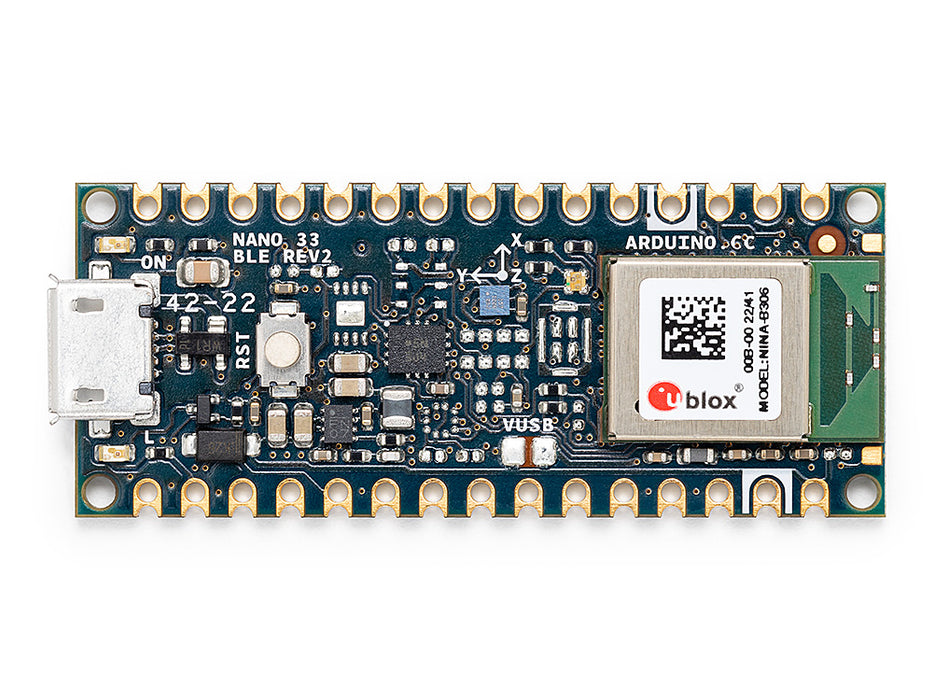
For full datasheet, photos, and dimensions see the Arduino Nano 33 BLE Rev2 product page.
Highlights
Nordic nRF52840 Cortex‑M4 with FPU at 64 MHz with 256 KB internal SRAM and 1 MB internal flash.
Bluetooth LE 5.0 via the on‑die radio and Nordic SoftDevice s140.
9‑axis IMU —
LSM9DS1on Rev 1,BMI270+BMM150on Rev 2. The frozenimudriver probes both at boot.LPS22HBbarometer,HTS221/HS3003temperature and humidity sensor,APDS9960ambient light / colour / proximity / gesture sensor, and MP34DT05 PDM microphone.Micro USB connector for power, programming, and a CDC REPL.
22 user I/O pins on the standard Nano headers —
TX/RX,D2–D13(digital),A0–A7(analog).
Pinout
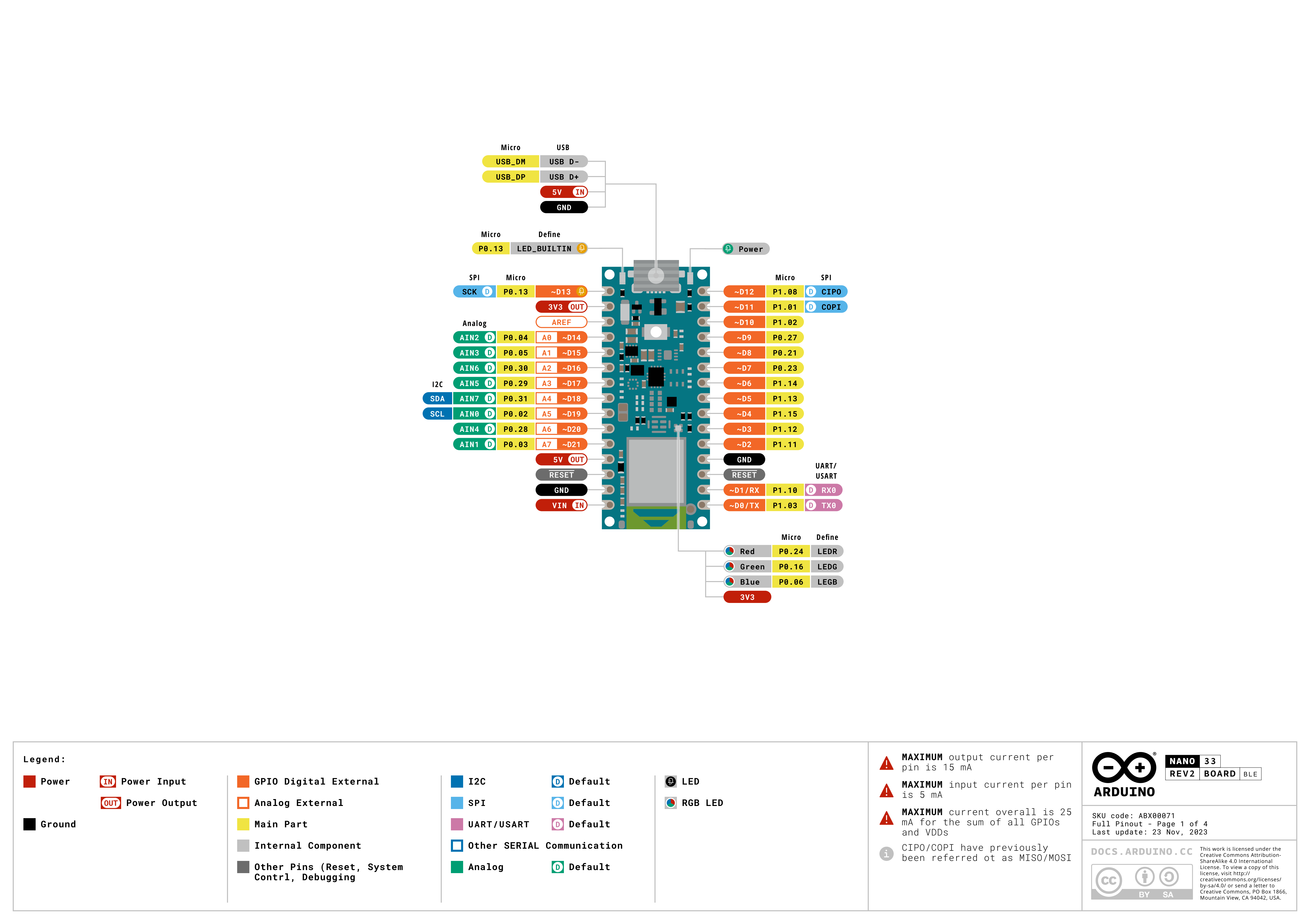
Pin reference
Pin name |
Reference |
Function |
|---|---|---|
TX |
3.3 V |
UART1 TX |
RX |
3.3 V |
UART1 RX |
D2 |
3.3 V |
PWM |
D3 |
3.3 V |
PWM |
D4 |
3.3 V |
PWM |
D5 |
3.3 V |
PWM |
D6 |
3.3 V |
PWM |
D7 |
3.3 V |
PWM |
D8 |
3.3 V |
PWM |
D9 |
3.3 V |
PWM |
D10 |
3.3 V |
PWM |
D11 |
3.3 V |
PWM / SPI0 MOSI |
D12 |
3.3 V |
PWM / SPI0 MISO |
D13 |
3.3 V |
PWM / SPI0 SCK |
A0 |
3.3 V |
ADC / PWM |
A1 |
3.3 V |
ADC / PWM |
A2 |
3.3 V |
ADC / PWM |
A3 |
3.3 V |
ADC / PWM |
A4 / I2C_SDA |
3.3 V |
ADC / PWM / I2C0 SDA |
A5 / I2C_SCL |
3.3 V |
ADC / PWM / I2C0 SCL |
A6 |
3.3 V |
ADC / PWM |
A7 |
3.3 V |
ADC / PWM |
RESET |
3.3 V |
press the on‑board RESET button or pull to GND to reset |
LED_BUILTIN |
— |
Orange user LED on |
LED_RED |
— |
RGB LED red channel (active low) |
LED_GREEN |
— |
RGB LED green channel (active low) |
LED_BLUE |
— |
RGB LED blue channel (active low) |
Warning
The Nano 33 BLE Sense’s I/O pins are 3.3 V only — they are not 5 V tolerant. Driving 5 V into them will damage the nRF52840.
Power pins
VIN — 4.5 – 21 V input. Powers the board through the on‑board regulator. Also fed via a diode from the USB 5 V rail, so USB and
VINcan be present at the same time without back‑driving each other.+5V — unconnected by default.
+3V3 — 3.3 V regulator output.
AREF — analog reference pin. Not wired to the nRF52840 on this board — the ADC is always referenced to 3.3 V.
GND — common ground.
The Nano 33 BLE Sense can be powered through either path:
Micro USB — supplies 5 V to the on‑board regulator.
VIN pin — drive a regulated 4.5 – 21 V supply.
Note
A solder jumper on the bottom of the board labelled VUSB
bridges +5V to the USB 5 V rail. Close it to make the
+5V header pin actually carry 5 V.
Note
A normally‑closed solder jumper on the output of the on‑board
4.5–21 V switching regulator can be cut to disable the regulator,
so the board can be powered directly from an external 3.3 V
supply on +3V3.
Recovery and debug pins
RESET — both an exposed pad and a momentary RESET button on the top of the board, tied to the nRF52840’s reset line. Pull to GND or press the button to reset.
The Nano 33 BLE Sense uses Arduino’s standard double‑tap reset to enter Arduino’s bootloader. Quickly press the RESET button twice — the board enters bootloader mode and OpenMV IDE can flash a new firmware image.
The nRF52840’s SWD signals are exposed on plated pads on the back of the board. All debug signals are 3.3 V referenced.
Onboard peripherals
LEDs
The Nano 33 BLE Sense has a user RGB LED — driven through the
silkscreened LED_RED, LED_GREEN, and LED_BLUE channels
— plus a separate orange LED_BUILTIN on D13. All four are
software‑controllable through machine.LED:
from machine import LED

LED("LED_RED").on()
LED("LED_GREEN").on()
LED("LED_BLUE").on()
LED("LED_BUILTIN").on()
A separate green power LED on the board lights whenever the +3.3 V rail is up and is not user‑controllable.
Camera sensor
The OpenMV firmware on the Nano 33 BLE Sense supports the OmniVision OV7670 parallel CMOS sensor. The board has no on‑board image sensor — wire an OV7670 module to the silkscreened header pins listed below and drive it through the csi — camera sensors module:
import csi

cam = csi.CSI()
cam.reset()
cam.pixformat(csi.RGB565)
cam.framesize(csi.QVGA)
cam.snapshot(time=2000)       # let auto‑exposure settle

while True:
    img = cam.snapshot()
Note
The OV7670 takes 14 pins. The firmware wires them as follows:
Sensor signal |
Nano 33 BLE Sense pin |
|---|---|
D0 |
|
D1 |
|
D2 |
|
D3 |
|
D4 |
|
D5 |
|
D6 |
|
D7 |
|
HSYNC |
|
VSYNC |
|
PXCLK |
|
MXCLK |
|
POWER |
|
RESET |
|
SCL |
|
SDA |
|
The OV7670’s I²C control bus is the same external I²C 0
exposed on A5/A4. The sensor sits at 7‑bit address
0x21 — user devices on that bus must avoid this address
when the camera is wired up.
IMU
The 9‑axis IMU is exposed through the frozen imu module, which
auto‑detects whether the board has the LSM9DS1 (Rev 1) or the
BMI270 + BMM150 (Rev 2) and presents a unified imu.IMU
class. The sensors sit on the internal I²C 1 bus (P14 /
P15):
import time
from machine import I2C, Pin
from imu import IMU

bus = I2C(1, scl=Pin("P15"), sda=Pin("P14"))
sensor = IMU(bus)

while True:
    print(sensor.accel())     # (x, y, z) in g
    print(sensor.gyro())      # (x, y, z) in deg/s
    print(sensor.magnet())    # (x, y, z) magnetometer
    time.sleep_ms(100)
For direct access to features like tap detection or the FIFO,
import the matching frozen driver (lsm9ds1, bmi270,
or bmm150) and instantiate it on the same bus.
Environmental sensors
The barometer (LPS22HB) and temperature /
humidity sensor (HTS221 on Rev 1,
HS3003 on Rev 2) share the same internal I²C 1 bus
as the IMU:
import time
from machine import I2C, Pin
from lps22h import LPS22H
from hts221 import HTS221

bus = I2C(1, scl=Pin("P15"), sda=Pin("P14"))
lps = LPS22H(bus)
try:
    hts = HTS221(bus)
except OSError:
    from hs3003 import HS3003
    hts = HS3003(bus)

while True:
    print("pressure:    %.2f hPa" % lps.pressure())
    print("temperature: %.2f C"   % lps.temperature())
    print("humidity:    %.2f %%"  % hts.humidity())
    time.sleep_ms(500)
Light / colour / proximity / gesture
The Broadcom APDS9960 sits on the same internal
I²C 1 bus and provides ambient light, RGB colour, proximity, and
gesture sensing:
import time
from machine import I2C, Pin
from apds9960 import uAPDS9960 as APDS9960

bus = I2C(1, scl=Pin("P15"), sda=Pin("P14"))
apds = APDS9960(bus)
apds.enableLightSensor()

while True:
    print("ambient light:", apds.readAmbientLight())
    time.sleep_ms(250)
Microphone
The on‑board MP34DT05 PDM microphone is captured through
audio — Audio Module. Each buffer arrives as signed‑16‑bit PCM
bytearray, ready to feed into ulab/numpy
for DSP:
import audio
from ulab import numpy as np

def loudness(pcmbuf):
    samples = np.array(np.frombuffer(pcmbuf, dtype=np.int16), dtype=np.float)
    rms = np.sqrt(np.mean(samples ** 2))
    if rms > 10000:
        print("Loud!", int(rms))

audio.init(channels=1, frequency=16000, gain_db=24)
audio.start_streaming(loudness)

while True:
    pass
Bluetooth
The nRF52840’s Bluetooth LE 5.0 radio runs on the Nordic
SoftDevice s140 and is exposed through the legacy ubluepy
module — the modern bluetooth / aioble — Async BLE
APIs are not enabled in this build. Both peripheral (GATT
server, advertise) and central (GAP observer / scanner +
connect) roles are available.
Advertise as a peripheral with a single Environmental Sensing
service and a notifiable temperature characteristic — the
event_handler callback fires on connect, disconnect, and CCCD
writes:
from ubluepy import Service, Characteristic, UUID, Peripheral, constants
from machine import LED

def event_handler(event_id, handle, data):
    if event_id == constants.EVT_GAP_CONNECTED:
        LED("LED_GREEN").on()
    elif event_id == constants.EVT_GAP_DISCONNECTED:
        LED("LED_GREEN").off()
        periph.advertise(device_name="Nano 33", services=[svc])

svc = Service(UUID("181A"))                          # Environmental Sensing
char = Characteristic(UUID("2A6E"),                  # Temperature
                      props=Characteristic.PROP_NOTIFY | Characteristic.PROP_READ,
                      attrs=Characteristic.ATTR_CCCD)
svc.addCharacteristic(char)

periph = Peripheral()
periph.addService(svc)
periph.setConnectionHandler(event_handler)
periph.advertise(device_name="Nano 33", services=[svc])
Scan for nearby advertising devices in central role:
from ubluepy import Scanner

for entry in Scanner().scan(1_000):                  # 1 second window
    print(entry.addr(), entry.rssi(), "dBm")
See the ubluepy reference for the full API — UUID, Service,
Characteristic,
Peripheral, Scanner, ScanEntry, and
the constants namespace.
Bus reference
GPIO
Use machine.Pin to read or drive any of the silkscreened pins. Outputs are 3.3 V CMOS — 15 mA per pin, 25 mA total across all GPIOs.
from machine import Pin

out = Pin("D2", Pin.OUT)
out.on()
out.off()
out.value(1)

inp = Pin("D3", Pin.IN, Pin.PULL_UP)
print(inp.value())
Any input pin can also fire an interrupt on edge transitions:
def handler(pin):
    print("triggered:", pin)

Pin("D3", Pin.IN, Pin.PULL_UP).irq(
    handler, Pin.IRQ_FALLING | Pin.IRQ_RISING,
)
UART
Bus |
TX |
RX |
|---|---|---|
UART1 |
TX |
RX |
Use the silkscreen names TX/RX with machine.UART:
from machine import UART

uart = UART(1, baudrate=115200)
uart.write("hello")
uart.read(5)
I²C
Bus |
SDA |
SCL |
|---|---|---|
I2C0 |
|
|
I2C1 |
|
|
Both buses need their pins passed explicitly to
machine.I2C:
from machine import I2C, Pin

bus0 = I2C(0, scl=Pin("I2C_SCL"), sda=Pin("I2C_SDA"), freq=400_000)
bus0.scan()

bus1 = I2C(1, scl=Pin("P15"), sda=Pin("P14"), freq=400_000)
bus1.scan()
Note
Bus 1 is the internal sensor bus on P14/P15 (not on the
user headers) — it serves the IMU, barometer, environmental
sensor, and APDS9960. The frozen sensor drivers use it directly;
user code can scan it too but the addresses are already taken
by the on‑board sensors.
SPI
Bus |
MOSI |
MISO |
SCK |
CS |
|---|---|---|---|---|
SPI0 |
D11 |
D12 |
D13 |
D10 |
The CS line is not driven by the SPI peripheral — configure
D10 as an output and toggle it manually around the transfer:
from machine import SPI, Pin

spi = SPI(0, baudrate=10_000_000)
cs = Pin("D10", Pin.OUT, value=1)   # CS is not driven by the SPI peripheral

cs.value(0)
spi.write(b"hello")
cs.value(1)
Note
D13 doubles as the orange LED_BUILTIN — driving SPI on
this bus will blink the LED in time with the bus clock.
ADC
The nRF52840 has eight 12‑bit ADC channels (SAADC) exposed on
A0–A7, all 3.3 V referenced — read_u16 returns
0–65535 across 0–3.3 V at the pin. The board’s AREF pin is
not wired, so the reference is always 3.3 V:
from machine import ADC
import time

adc = ADC("A0")
while True:
    voltage = adc.read_u16() * 3.3 / 65535
    print(voltage)
    time.sleep_ms(100)
PWM
The nRF52840 exposes four PWM peripherals (PWM0–PWM3),
each driving four channels, for 16 hardware PWM slots in
total. Unlike fixed‑function ports, the peripherals route through
the GPIOTE matrix — any GPIO can be a PWM output, so there is
no pin‑to‑slice mapping. The cost of that flexibility is two
constraints baked into the silicon:
All four channels inside a module share a single period/frequency.
Each channel has its own duty cycle and polarity.
Conceptually the 16 slots look like this:
Module |
Ch 0 |
Ch 1 |
Ch 2 |
Ch 3 |
|---|---|---|---|---|
PWM0 |
duty |
duty |
duty |
duty |
PWM1 |
duty |
duty |
duty |
duty |
PWM2 |
duty |
duty |
duty |
duty |
PWM3 |
duty |
duty |
duty |
duty |
Each row runs at one frequency; the four cells in a row each drive an independently‑chosen pin with its own duty cycle. Different rows can run at completely different frequencies.
Drive any silkscreened pin (or the on‑board LEDs) via machine.PWM:
from machine import Pin, PWM

pwm = PWM(Pin("D3"), freq=1_000, duty_u16=32768)
Warning
Auto‑allocation consumes a whole module per call. When you
create a PWM without device=/channel= kwargs, the
driver grabs the first free module and binds your pin to its
channel 0 only. The remaining three channels of that module
sit idle and are only reachable through explicit
device=/channel=. That caps unaided PWM(Pin(...))
calls at four before the driver raises
ValueError: all PWM devices in use — even though twelve
slots are technically still free.
To use more than four PWMs, or to deliberately share a frequency
across pins, pass device (0–3) and channel (0–3):
# Two PWMs on the same module → forced to share frequency,
# but each gets its own duty cycle.
pwm_a = PWM(Pin("D3"), device=0, channel=0,
            freq=1_000, duty_u16=32768)
pwm_b = PWM(Pin("D5"), device=0, channel=1,
            freq=1_000, duty_u16=16384)

# A third PWM on a separate module, free to pick any frequency.
pwm_c = PWM(Pin("D6"), device=1, channel=0,
            freq=20_000, duty_u16=49152)
Duty cycle accepts duty (0–100%), duty_u16 (0–65535), or
duty_ns. Add invert=1 to flip the output polarity (handy
for the active‑low RGB LED).
Note
Because frequency is a per‑module property, calling
pwm.freq(new_freq) on any channel of a module re‑runs
nrfx_pwm_init for the whole module and changes the
frequency seen by every other channel sharing it.
Note
Allowed frequencies span roughly 4 Hz to 5.3 MHz, derived
from the 16 MHz base clock with prescalers 1/2/4/8/16/32/64/128
and a 15‑bit period counter. The driver picks the closest divisor
automatically — freq() reports the requested value, not the
exact achievable one.
Software bit‑banged buses
machine.SoftI2C and machine.SoftSPI work on any GPIO if you need an extra bus.
Thermal sensor (off‑board)
The firmware includes the fir — thermal sensor driver (fir == far infrared) driver for externally wired thermal imagers:
MLX90621 — 16 × 4 IR array
MLX90640 — 32 × 24 IR array
MLX90641 — 16 × 12 IR array
AMG8833 — 8 × 8 IR array
Wire the module to the board’s I²C bus and read frames with
fir.init() + fir.snapshot():
import time
import image
import fir

fir.init()                          # auto‑detects the sensor
clock = time.clock()

while True:
    clock.tick()
    try:
        img = fir.snapshot(x_scale=5, y_scale=5,
                           color_palette=image.PALETTE_IRONBOW,
                           hint=image.BICUBIC,
                           copy_to_fb=True)
    except OSError:
        continue
    print(clock.fps())
The fir driver only talks to the sensor over I²C 0 — wire
the module to the I2C_SCL / I2C_SDA pads
(A5 / A4).
Timing
time
The time module covers blocking delays, monotonic ticks, and
elapsed‑time measurement:
import time

time.sleep(1)              # seconds
time.sleep_ms(500)
time.sleep_us(10)

start = time.ticks_ms()
# ...do work...
elapsed = time.ticks_diff(time.ticks_ms(), start)
Virtual timers
machine.Timer schedules periodic or one‑shot
callbacks without consuming a hardware timer slot. Pass -1 as the
id to use a virtual (software) timer:
from machine import Timer

one_shot = Timer(-1)
one_shot.init(period=5_000, mode=Timer.ONE_SHOT,
              callback=lambda t: print("once"))

periodic = Timer(-1)
periodic.init(period=2_000, mode=Timer.PERIODIC,
              callback=lambda t: print("tick"))
Period values are in milliseconds. Call deinit()
to stop and release the slot.
Real‑time clock
machine.RTC keeps wall‑clock time across resets. The nRF52840’s RTC is tied to the on‑chip oscillator and does not survive full power loss — set the time on every cold boot if it matters to your application:
from machine import RTC

rtc = RTC()
rtc.datetime((2026, 4, 30, 4, 12, 0, 0, 0))   # Y, M, D, weekday, h, m, s, subsec
print(rtc.datetime())
Watchdog
machine.WDT resets the board if the application hangs. Once started it can’t be stopped or reconfigured — feed it periodically inside your main loop:
from machine import WDT

wdt = WDT(timeout=5_000)   # 5 second window
while True:
    # ...do work...
    wdt.feed()
Boot and runtime info
Firmware update
The Nano 33 BLE Sense uses Arduino’s standard double‑tap reset to enter Arduino’s bootloader. Quickly press the RESET button twice — the board enters bootloader mode and OpenMV IDE can flash a new firmware image.
A running script can re‑enter the bootloader on demand by calling
machine.bootloader():
import machine

machine.bootloader()
Filesystem and boot order
The Nano 33 BLE Sense firmware mounts a single filesystem on boot:
Internal flash — always mounted at
/flashand used as the working directory. Holdsmain.pyandREADME.txtby default; created on the very first boot.
After mounting, the interpreter then runs scripts from /flash:
boot.pyis executed on every soft reset.main.pyis executed only on cold boot, immediately afterboot.py.
The default main.py shipped on a freshly flashed board just
blinks the user RGB LED’s blue channel as a heartbeat (two
short pulses, short gap), so you can tell the firmware booted
cleanly without any host attached.
/flash is not exposed as a USB mass‑storage drive on this
board.
Storage sizes
The Nano 33 BLE Sense ships with:
/flash— 64 KB FAT filesystem, read/write.
The Nano 33 BLE Sense build does not include a ROMFS; ship Python
modules on /flash directly.
Software libraries
See the library index for the full list of modules — including which ones are unique to the Nano 33 BLE Sense build.