OpenMV N6
The OpenMV N6 is built around the STMicroelectronics STM32N657 (Cortex‑M55 @ 800 MHz) with a 1 GHz on‑chip NPU rated at 600 GOPS INT8. The board pairs the NPU with the PAG7936 1 MP global‑shutter sensor on a removable carrier, gigabit Ethernet, USB‑C high‑speed, Wi‑Fi, and Bluetooth 5.1, and runs YOLOv8/YOLOv11 inference at 30 FPS alongside live video streaming.
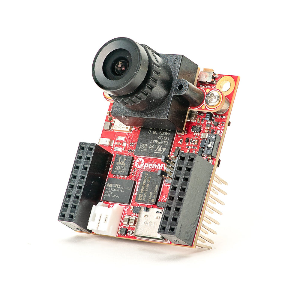
For full datasheet, photos, and dimensions see the OpenMV N6 product page.
Highlights
STM32N657 Cortex‑M55 at 800 MHz (1280 DMIPS) with ARM Helium 128‑bit SIMD — 6.4 gigaops vector throughput.
1 GHz NPU, 600 GOPS INT8 — runs YOLOv8/YOLOv11 detection at 30 FPS.
ISP for up to 5MP RAW Bayer, 2D GPU for scaling and 3D rotation, H.264 encode to 1080p, and hardware JPEG codec.
64 MB external SDRAM (16‑bit @ 200 MHz DDR, 800 MB/s) plus 4.2 MB internal SRAM and 32 MB octal flash (200 MHz DDR, 400 MB/s).
PAG7936 1 MP color global‑shutter sensor.
Onboard IMU (accelerometer + gyroscope) and microphone for audio + motion fusion.
High‑speed USB‑C (480 Mb/s, 1.5 A current limit), gigabit Ethernet (PoE‑capable via shield), Wi‑Fi a/b/g/n + Bluetooth 5.1 (chip antenna or U.FL option).
microSD socket — SD up to 2 GB, SDHC up to 32 GB, SDXC up to 2 TB.
LiPo charger (500 mA fast charge), battery‑voltage ADC, RTC with 8 KB backup RAM and a dedicated backup‑battery pin.
18 I/O pins, all 3.3 V output / 3.3 V tolerant, 20 mA per pin, interrupt‑capable.
User RGB LED, user button, and a separate status LED for charging / USB / VIN power.
Warning
The N6’s I/O pins are not 5 V tolerant. Do not connect the device directly to a 5 V MCU like the Arduino Mega. Power the N6 through VIN only.
Pinout
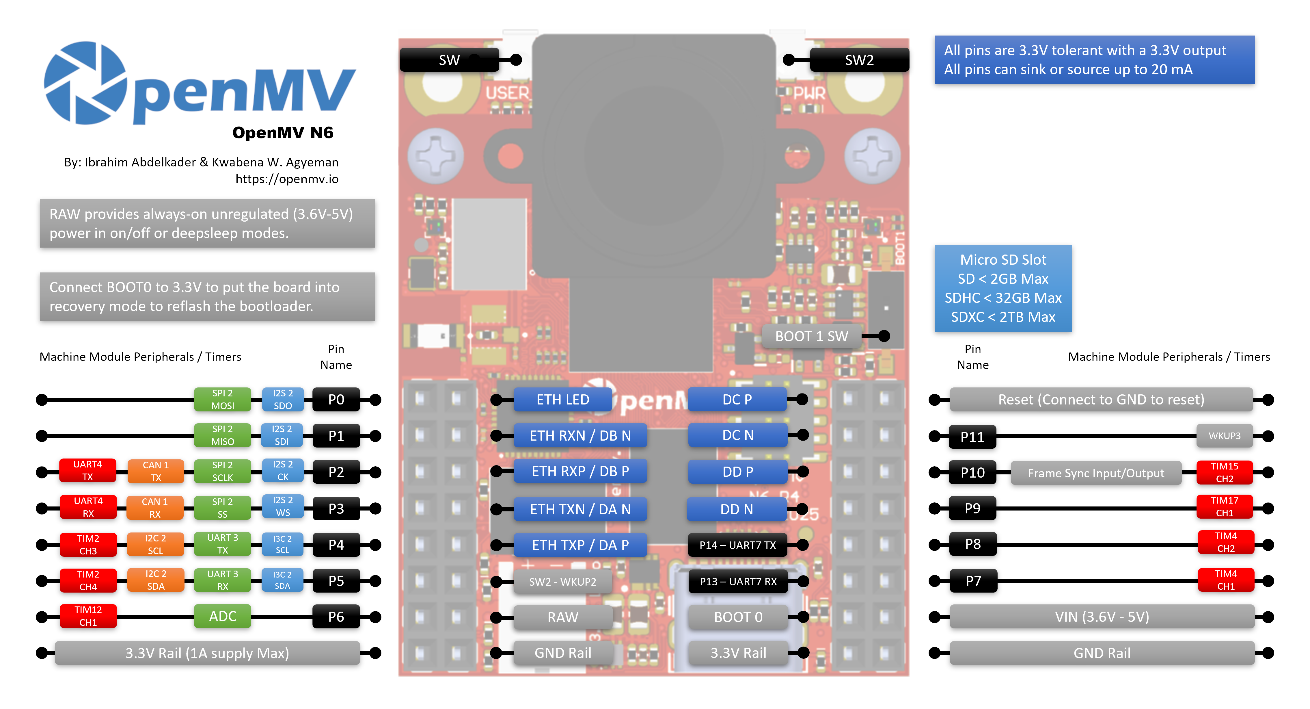
Pin reference
Pin name |
Function |
|---|---|
P0 |
SPI2 MOSI / I2S2 SDO |
P1 |
SPI2 MISO / I2S2 SDI |
P2 |
SPI2 SCLK / UART4 TX / CAN1 TX / I2S2 CK |
P3 |
SPI2 SS / UART4 RX / CAN1 RX / I2S2 WS |
P4 |
I2C2 SCL / UART3 TX / TIM2 CH3 / I3C2 SCL |
P5 |
I2C2 SDA / UART3 RX / TIM2 CH4 / I3C2 SDA |
P6 |
TIM12 CH1 (no ADC on this pin — see |
P6_ADC |
dedicated 12‑bit ADC input (tied internally to P6) |
P7 |
TIM4 CH1 |
P8 |
TIM4 CH2 |
P9 |
TIM17 CH1 |
P10 |
TIM15 CH2 / frame sync I/O |
P11 |
wakeup (active low, WKUP3) |
P12 |
RESET — pull to GND to reset the board (not a GPIO) |
P13 |
UART7 RX |
P14 |
UART7 TX |
P15 |
SPI4 CS |
P16 |
SPI4 SCK |
P17 |
SPI4 MISO |
P18 |
SPI4 MOSI |
SW |
user button (active low) |
ONOFF (SW2) |
deep‑sleep wakeup button (active low, WKUP2) |
ST |
low on VIN power, high on USB power |
CHG |
active‑low; low while an attached LiPo battery is charging |
PG |
active‑low; low when VIN or USB power is present |
BAT_ADC |
internal ADC channel measuring the attached LiPo battery voltage |
LED_RED |
RGB LED red channel (active low) |
LED_GREEN |
RGB LED green channel (active low) |
LED_BLUE |
RGB LED blue channel (active low) |
Note
The P10 frame‑sync line is a shared bus. It is wired to the MCU, the camera sensor’s trigger / exposure pin, and the user header all at once. Direction is application‑defined — the MCU, the sensor, or an external signal can drive it depending on how the sensor is configured (some sensors can use the same pin as a trigger input or an exposure output). Make sure only one driver is active at a time.
Note
ONOFF and P11 are referenced to the always‑on RAW rail (not the switched 3.3 V rail), so they remain functional while the rest of the board is in deep sleep / low‑power mode. Both inputs are active low.
These pins go through level shifters so they can ride on the RAW rail. If you absolutely need 3.3 V‑direct GPIO behaviour on ONOFF or P11 (for example to drive them from a 3.3 V MCU without going through the shifter), the board exposes pull‑up and 0‑ohm jumper pads that let you bypass the shifter. This is an advanced hardware rework — most users should leave it alone.
Note
P15–P18 are shared with the Gigabit Ethernet PHY, which is wired up and active by default. To use these pins as user I/O you must reflow the 0‑ohm resistor on the back of the board over to the GPIO position. This only disables gigabit Ethernet — 10/100 Mb/s Ethernet keeps working on its dedicated pins.
Power pins
3.3V — regulated 3.3 V rail. Output only on the N6 — do not feed external power into this pin. Up to 1 A available for shields.
VIN — 5 V input. Powers the board and the on‑board LiPo charger.
RAW — input/output, always‑on (3.6 V – 5 V). Carries whichever source is active (VIN, USB, or attached battery), and can also be used as an input. You must drive RAW through a series diode when sourcing power into it — otherwise current will flow back into VIN/USB and damage the supply or the on‑board protection.
GND — common ground.
Note
The on‑board power management chip automatically picks whichever of USB or VIN has the higher voltage to power the board and the battery charger. If a LiPo is attached it charges on the leftover headroom, and the controller falls back to the battery to keep the board running if VIN/USB sag or are unplugged.
Note
The back of the board has solder pads for an external 3.3 V RTC backup battery. Wiring a coin cell to these pads keeps the RTC and 8 KB of backup RAM running while the rest of the board is unpowered.
Tip
Use the battery life estimator to model how long the N6 will run on a battery for a given active / deep-sleep duty cycle.
Ethernet pins
The N6 exposes the Ethernet PHY’s MDI pairs on dedicated pads next to the GPIO header. The MDI pins are not safe to wire straight to an RJ45 — Ethernet magnetics (an isolation transformer, either built into a magjack or on the shield) are required between the PHY and the cable. The OpenMV PoE shield includes them; if you’re rolling your own jack, use a magnetics‑integrated RJ45 or an external transformer.
ETH_LED — link/activity LED. Active low when a link is up; flashes on traffic.
DA P / DA N — pair A (TX in 10/100, used by all speeds).
DB P / DB N — pair B (RX in 10/100, used by all speeds).
DC P / DC N — pair C, only used at gigabit.
DD P / DD N — pair D, only used at gigabit.
10/100 Mb/s only needs pairs A and B. Gigabit needs all four pairs A–D.
Recovery and debug pins
RESET — pull to GND to reset the board. Releasing it lets the MCU start up normally.
BOOT0 — pull to 3.3 V while powering the board to enter ROM bootloader mode. OpenMV IDE uses this mode to reflash the on‑board bootloader.
BOOT1 — switch that puts the board into developer mode for use with ST’s tooling (an ST‑LINK attached to the ARM 10‑pin SWD/JTAG header). Leave this disabled for normal operation with OpenMV firmware and tools.
A dedicated ARM 10‑pin SWD/JTAG header is fitted, compatible with ST‑LINK and SEGGER J‑Link adapters.
Onboard peripherals
LEDs
The N6 has two RGB LEDs:
User RGB LED — software‑controllable, exposed as
LED_RED,LED_GREENandLED_BLUE:from machine import LED LED("LED_RED").on() LED("LED_GREEN").on() LED("LED_BLUE").on()
Power LED — driven directly by the on‑board power management hardware, no software control. Use it to read what the supply is doing at a glance.
While running:
Channel
Meaning
Blue
VIN is powering the board (off on USB)
Green
USB or VIN power present
Red
charging an attached LiPo battery
In deep sleep all channels are off except Red, which still lights while a LiPo is charging.
Power status pins
Three active‑low status inputs let firmware see what the on‑board power management chip is doing:
ST — low when the board is running on VIN, high when running on USB power.
CHG — low while an attached LiPo battery is charging.
PG — low when VIN or USB power is present.
from machine import Pin

on_vin    = not Pin("ST",  Pin.IN).value()
charging  = not Pin("CHG", Pin.IN).value()
power_ok  = not Pin("PG",  Pin.IN).value()
Camera sensor
The PAG7936 is driven through the csi — camera sensors module:
import csi

cam = csi.CSI()
cam.reset()
cam.pixformat(csi.RGB565)
cam.framesize(csi.HD)         # 1280×800
cam.snapshot(time=2000)       # let auto‑exposure settle

while True:
    img = cam.snapshot()
The sensor sits on a removable module — swap it for any of the other OpenMV camera modules (global shutter, thermal, higher resolution, etc.) without changing the rest of the board.
The PAG7936 supports triggered mode — pixel integration lines up
exactly with each csi.CSI.snapshot call rather than the
free-running frame clock, useful for syncing capture to an
external event or another sensor. Enable it through
csi.CSI.ioctl with csi.IOCTL_SET_TRIGGERED_MODE. Frame rate
drops to roughly half of free-running mode because the readout no
longer pipelines with the next frame’s integration:
cam.ioctl(csi.IOCTL_SET_TRIGGERED_MODE, True)
NPU
The N6’s 1 GHz Neural‑ART NPU (600 GOPS INT8) is exposed through the
ml — Machine Learning module. Models stored on the read‑only /rom
filesystem load directly from flash without copying to RAM, so even
large detectors fit comfortably alongside the live framebuffer. Run
a YOLOv8 detector on every frame and draw the predictions on top of
the live image:
import csi
import time
import ml
from ml.postprocessing.ultralytics import YoloV8

# Initialize the sensor.
csi0 = csi.CSI()
csi0.reset()
csi0.pixformat(csi.RGB565)
csi0.framesize(csi.VGA)

# Load YOLO V8 model from ROM FS.
model = ml.Model("/rom/yolov8n_192.tflite", postprocess=YoloV8(threshold=0.4))
print(model)

# Visualization parameters.
n = len(model.labels)
model_class_colors = [
    (int(255 * i // n), int(255 * (n - i - 1) // n), 255)
    for i in range(n)
]

clock = time.clock()
while True:
    clock.tick()
    img = csi0.snapshot()

    # boxes is a list of list per class of ((x, y, w, h), score) tuples
    boxes = model.predict([img])

    # Draw bounding boxes around the detected objects
    for i, class_detections in enumerate(boxes):
        rects = [r for r, score in class_detections]
        labels = [model.labels[i] for j in range(len(rects))]
        colors = [model_class_colors[i] for j in range(len(rects))]
        ml.utils.draw_predictions(img, rects, labels, colors, format=None)

    print(clock.fps(), "fps")
Microphone
The on‑board mic is captured through audio — Audio Module. Each
buffer arrives as a signed‑16‑bit PCM bytearray, which makes it
trivial to feed into ulab/numpy for
quick DSP. A simple loudness detector — print whenever the RMS volume
crosses a threshold:
import audio
from ulab import numpy as np

def loudness(pcmbuf):
    samples = np.array(np.frombuffer(pcmbuf, dtype=np.int16), dtype=np.float)
    rms = np.sqrt(np.mean(samples ** 2))
    if rms > 10000:
        print("Loud!", int(rms))

audio.init(channels=1, frequency=16000, gain_db=24)
audio.start_streaming(loudness)

while True:
    pass
IMU
The on‑board accelerometer + gyroscope under the camera module is exposed through imu — imu sensor:
import imu
import time

while True:
    print(imu.acceleration_mg())   # (x, y, z) in milli‑g
    print(imu.angular_rate_mdps()) # (x, y, z) in milli‑deg/s
    time.sleep_ms(100)
Wi‑Fi
The on‑board CYW43439 is exposed via network — network configuration as a
station interface. After connecting, ipconfig("addr4") returns the
(ip, netmask) pair:
import network, time

wlan = network.WLAN(network.STA_IF)
wlan.active(True)
wlan.connect("ssid", "password")
while not wlan.isconnected():
    time.sleep(1)
print("Wi‑Fi IP:", wlan.ipconfig("addr4")[0])
Bluetooth
The same CYW43439 also exposes Bluetooth 5.1. Use aioble — Async BLE for asyncio‑friendly BLE — for example, advertise as a peripheral and wait for a central to connect:
import asyncio
import aioble

async def run():
    while True:
        conn = await aioble.advertise(250_000, name="OpenMV-N6")
        print("Connected:", conn.device)
        await conn.disconnected()

asyncio.run(run())
Ethernet
When an RJ45 (with magnetics) is connected to the MDI pads, the gigabit
PHY appears as a LAN interface. DHCP runs automatically once the
link comes up:
import network, time

lan = network.LAN()
lan.active(True)
while not lan.isconnected():
    time.sleep(1)
print("Ethernet IP:", lan.ipconfig("addr4")[0])
microSD card
When a card is inserted it is mounted automatically at /sdcard and
is usable through the regular file system:
import os

for entry in os.listdir("/sdcard"):
    print(entry)
Bus reference
GPIO
Use machine.Pin to read or drive any of the silkscreened pins. Outputs are 3.3 V CMOS and can sink/source up to 20 mA per pin.
from machine import Pin

out = Pin("P0", Pin.OUT)
out.on()
out.off()
out.value(1)

inp = Pin("P1", Pin.IN, Pin.PULL_UP)
print(inp.value())
Any input pin can also fire an interrupt on edge transitions:
def handler(pin):
    print("triggered:", pin)

Pin("P1", Pin.IN, Pin.PULL_UP).irq(
    handler, Pin.IRQ_FALLING | Pin.IRQ_RISING,
)
UART
Bus |
TX |
RX |
|---|---|---|
UART3 |
P4 |
P5 |
UART4 |
P2 |
P3 |
UART7 |
P14 |
P13 |
from machine import UART

uart = UART(3, baudrate=115200)
uart.write("hello")
uart.read(5)
I²C
Bus |
SCL |
SDA |
|---|---|---|
I2C2 |
P4 |
P5 |
from machine import I2C

i2c = I2C(2, freq=400_000)
i2c.scan()
i2c.writeto(0x76, b"hi")
The same hardware can also be used in target (slave) mode through machine.I2CTarget to expose a memory region to another I²C controller:
from machine import I2CTarget

buf = bytearray(32)
target = I2CTarget(2, addr=0x42, mem=buf)
SPI
Bus |
MOSI |
MISO |
SCK |
CS |
|---|---|---|---|---|
SPI2 |
P0 |
P1 |
P2 |
P3 |
SPI4 |
P18 |
P17 |
P16 |
P15 |
from machine import SPI
from machine import Pin

spi = SPI(2, baudrate=10_000_000)
cs = Pin("P3", Pin.OUT, value=1)   # CS is not driven by the SPI peripheral

cs.value(0)
spi.write(b"hello")
cs.value(1)
CAN
Bus |
TX |
RX |
|---|---|---|
CAN1 |
P2 |
P3 |
Note
CAN is not yet supported on this board in firmware v5.0.0.
from machine import CAN

can = CAN(1, 500_000)
can.set_filters(None)
can.send(0x123, b"\xDE\xAD\xBE\xEF")
print(can.recv())
ADC
Both ADC channels go through an op‑amp buffered voltage divider before
hitting the MCU, so read_u16() is mapped to a different full‑scale
input voltage on each pin.
Pin |
Full‑scale |
Notes |
|---|---|---|
P6_ADC |
~3.3 V |
general‑purpose pad, tied internally to P6 |
BAT_ADC |
~5.0 V |
internal channel for the LiPo battery |
from machine import ADC
import time

adc = ADC("P6_ADC")
bat = ADC("BAT_ADC")

while True:
    print("P6:", adc.read_u16() * 3.3 / 65535, "V")
    print("BAT:", bat.read_u16() * 5.0 / 65535, "V")
    time.sleep_ms(100)
PWM
Pin |
Timer / channel |
|---|---|
P4 |
TIM2 CH3 |
P5 |
TIM2 CH4 |
P6 |
TIM12 CH1 |
P7 |
TIM4 CH1 |
P8 |
TIM4 CH2 |
P9 |
TIM17 CH1 |
P10 |
TIM15 CH2 |
Drive any of them via machine.PWM:
from machine import Pin, PWM

pwm = PWM(Pin("P6"), freq=1_000, duty_u16=32768)
Software bit‑banged buses
machine.SoftI2C and machine.SoftSPI work on any GPIO if you need an extra bus.
Thermal sensor (off‑board)
The firmware includes the fir — thermal sensor driver (fir == far infrared) driver for externally wired thermal imagers:
MLX90621 — 16 × 4 IR array
MLX90640 — 32 × 24 IR array
MLX90641 — 16 × 12 IR array
AMG8833 — 8 × 8 IR array
Wire the module to the board’s I²C bus and read frames with
fir.init() + fir.snapshot():
import time
import image
import fir

fir.init()                          # auto‑detects the sensor
clock = time.clock()

while True:
    clock.tick()
    try:
        img = fir.snapshot(x_scale=5, y_scale=5,
                           color_palette=image.PALETTE_IRONBOW,
                           hint=image.BICUBIC,
                           copy_to_fb=True)
    except OSError:
        continue
    print(clock.fps())
The fir driver only talks to the sensor over I²C 2 — wire
the module to P4 (SCL) and P5 (SDA).
Timing
time
The time module covers blocking delays, monotonic ticks, and
elapsed‑time measurement:
import time

time.sleep(1)              # seconds
time.sleep_ms(500)
time.sleep_us(10)

start = time.ticks_ms()
# ...do work...
elapsed = time.ticks_diff(time.ticks_ms(), start)
Virtual timers
machine.Timer schedules periodic or one‑shot
callbacks without consuming a hardware timer slot. Pass -1 as the
id to use a virtual (software) timer:
from machine import Timer

one_shot = Timer(-1)
one_shot.init(period=5_000, mode=Timer.ONE_SHOT,
              callback=lambda t: print("once"))

periodic = Timer(-1)
periodic.init(period=2_000, mode=Timer.PERIODIC,
              callback=lambda t: print("tick"))
Period values are in milliseconds. Call deinit()
to stop and release the slot.
Real‑time clock
machine.RTC keeps wall‑clock time across resets and (with the optional 3.3 V backup battery wired to the rear pads, see Power pins) across full power loss:
from machine import RTC

rtc = RTC()
rtc.datetime((2026, 4, 30, 4, 12, 0, 0, 0))   # Y, M, D, weekday, h, m, s, subsec
print(rtc.datetime())
The RTC also runs through deep sleep, so you can use it as a wakeup
source for machine.deepsleep().
Watchdog
machine.WDT resets the board if the application hangs. Once started it can’t be stopped or reconfigured — feed it periodically inside your main loop:
from machine import WDT

wdt = WDT(timeout=5_000)   # 5 second window
while True:
    # ...do work...
    wdt.feed()
Boot and runtime info
USB bootloader window
On every power‑up the camera runs a short bootloader (a few seconds)
that lets OpenMV IDE update the firmware without the user having to
enter DFU mode. After the window expires the bootloader hands off to
boot.py and then main.py.
A running script can re‑enter the bootloader on demand by calling
machine.bootloader():
import machine

machine.bootloader()
Filesystem and boot order
The N6 firmware mounts up to three filesystems on boot:
Internal flash — always mounted at
/flash. Holdsmain.pyandREADME.txtby default; created on the very first boot.microSD card — if a card is inserted it is mounted at
/sdcard.ROMFS — read‑only, memory‑mapped filesystem at
/romused to ship large data assets (e.g. AI models) that benefit from zero‑copy access. Mounted automatically by MicroPython at startup, before any user Python runs.
After mounting, the working directory is set to /sdcard when the
card is present, otherwise /flash. The interpreter then runs
scripts from that directory:
boot.pyis executed on every soft reset (cold boot,Ctrl‑Dfrom the REPL, or whenever the running script returns).main.pyis executed only on cold boot, immediately afterboot.py. Subsequent soft resets re‑runboot.pybut drop straight to the REPL — to re‑runmain.pyyou have to fully reset the board.
Dropping a boot.py or main.py onto the SD card overrides the
copy in flash without touching it — both files are looked up in the
boot directory (/sdcard when the card is mounted, otherwise
/flash).
The default main.py shipped on a freshly flashed board just blinks
the user RGB LED’s blue channel as a heartbeat (two short pulses,
short gap), so you can tell the firmware booted cleanly without any
host attached.
sys.path is extended to include all three filesystems and their
lib/ subdirectories, so importable modules can live in
/flash/lib, /sdcard/lib, or /rom/lib.
To force the system to ignore an inserted SD card (for example to run
the flash main.py even with a card present), create an empty file
named SKIPSD at the root of /flash.
When connected over USB, the boot filesystem (/sdcard if a card is
present, otherwise /flash) also enumerates as a USB mass‑storage
drive on the host, letting you edit boot.py, main.py, and any
other files directly. Eject the drive before resetting the camera
so the host flushes its cached writes.
Note
Because the OS treats the drive as a passive block device, files created or modified by code running on the OpenMV Cam will not show up until the host re‑mounts the drive. If both the OS and the OpenMV Cam write the same filesystem at the same time, the OS will win and overwrite changes made by the camera. Use the SD card for any data the script writes back, and remount before reading those files from the host.
Note
The user RGB LED’s red channel may briefly light up while the host is reading from or writing to the USB mass‑storage drive — this is a firmware‑driven activity indicator, not a fault.
Storage sizes
The N6 ships with:
/flash— 4 MB FAT filesystem, read/write./rom— 24 MB read-only memory-mapped ROMFS, used to ship scripts and ML models that benefit from zero-copy mmap access./sdcard— full size of whatever microSD card is inserted (when present), read/write.
Hard‑fault indicator
If the user RGB LED is rapidly cycling through all colours — fast enough that it tends to look like a twinkling white LED rather than distinct hues — the firmware has hit an unrecoverable hard fault. Reflash the firmware to recover; if reflashing doesn’t help, the board may be physically damaged.
Software libraries
See the library index for the full list of modules — including which ones are unique to the N6 build.