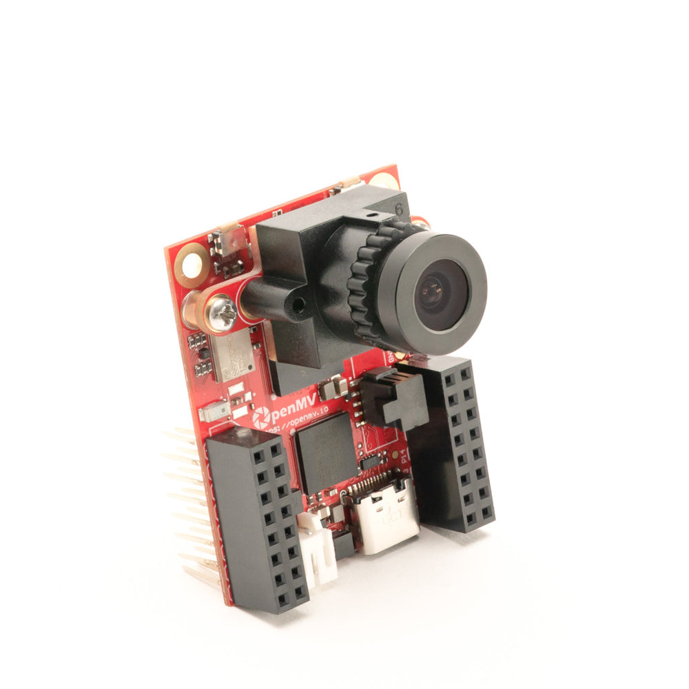
OpenMV Cam RT1062
The OpenMV Cam RT1062 is a low‑power machine‑vision board built around the NXP i.MX RT1062 (Cortex‑M7 @ 600 MHz). The board pairs USB‑C high‑speed networking, Wi‑Fi/Bluetooth, and 10/100 Ethernet with an OV5640 5MP sensor on a removable carrier. The camera only draws ~30 µA from a LiPo battery in deep sleep, which makes it well suited to battery‑powered projects.
For full datasheet, photos, and dimensions see the OpenMV Cam RT1062 product page.
Highlights
NXP i.MX RT1062 Cortex‑M7 at 600 MHz.
32 MB external SDRAM (16‑bit @ 160 MHz, 320 MB/s) plus 1 MB internal SRAM and 16 MB QSPI flash (133 MHz 4‑bit SDR, 66 MB/s read); 4 KB EEPROM on R6+.
OV5640 5MP rolling‑shutter sensor.
Onboard IMU (12‑bit 3‑axis accelerometer, ±2/4/8 g).
High‑speed USB‑C (480 Mb/s, 1.5 A current limit), 10/100 Mb/s Ethernet (PoE‑capable via shield), Wi‑Fi a/b/g/n + Bluetooth 5.1 (chip antenna or U.FL option).
microSD socket — SD up to 2 GB, SDHC up to 32 GB, SDXC up to 2 TB.
LiPo charger (500 mA on R6+, 100 mA on R4/R5), RTC with backup‑battery pads. Deep sleep draws ~30 µA on battery.
14 I/O pins, all 3.3 V output / 3.3 V tolerant, 4 mA per pin, interrupt‑capable.
User RGB LED, user SW button, hardware power button (deep‑sleep / wake state machine), and a separate status LED for charging / USB / VIN power.
Warning
The RT1062’s I/O pins are not 5 V tolerant. Do not connect the device directly to a 5 V MCU like the Arduino Mega. Power the board through VIN only.
Pinout
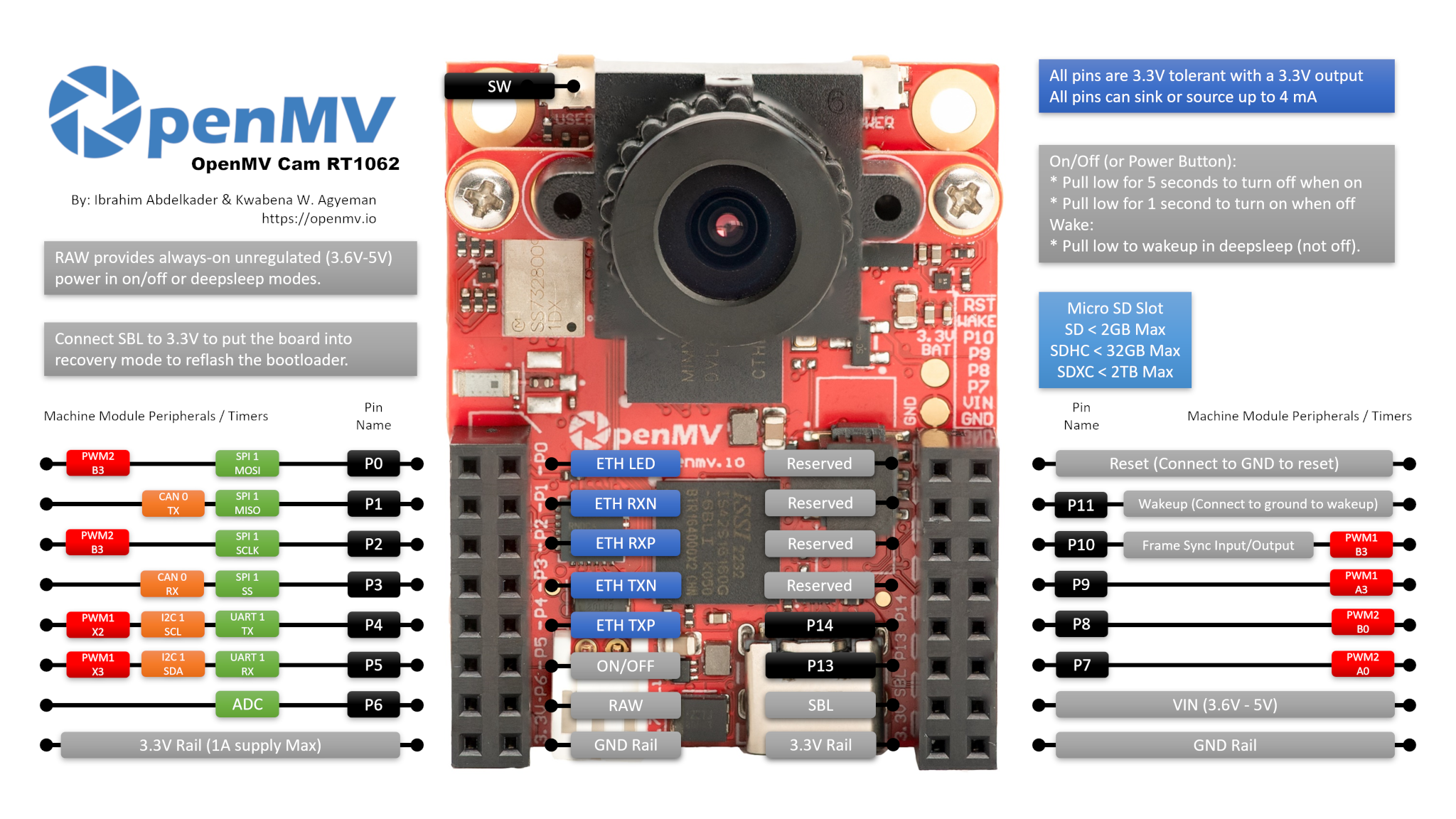
Pin reference
Pin name |
Function |
|---|---|
P0 |
SPI1 MOSI / PWM2 B3 |
P1 |
SPI1 MISO / CAN0 TX |
P2 |
SPI1 SCLK / PWM2 B3 |
P3 |
SPI1 SS / CAN0 RX |
P4 |
I2C1 SCL / UART1 TX / PWM1 X2 |
P5 |
I2C1 SDA / UART1 RX / PWM1 X3 |
P6 |
ADC |
P7 |
PWM2 A0 |
P8 |
PWM2 B0 |
P9 |
PWM1 A3 |
P10 |
PWM1 B3 / frame sync I/O |
P11 |
wakeup (active low, connect to GND to wake) |
P12 |
RESET — pull to GND to reset the board (not a GPIO) |
P13 |
digital I/O |
P14 |
digital I/O |
ON/OFF |
header pad replicating the hardware power button (active low) |
SW |
user button (active low) |
ST |
low on VIN power, high on USB power |
CHG |
active‑low; low while an attached LiPo battery is charging |
PG |
active‑low; low when VIN or USB power is present |
LED_RED |
RGB LED red channel (active low) |
LED_GREEN |
RGB LED green channel (active low) |
LED_BLUE |
RGB LED blue channel (active low) |
Note
The P10 frame‑sync line is a shared bus. It is wired to the MCU, the camera sensor’s trigger / exposure pin, and the user header all at once. Direction is application‑defined — the MCU, the sensor, or an external signal can drive it depending on how the sensor is configured. Make sure only one driver is active at a time.
Note
ON/OFF and P11 are referenced to the always‑on RAW rail (not the switched 3.3 V rail), so they remain functional while the rest of the board is in deep sleep / low‑power mode. Both inputs are active low.
These pins go through level shifters so they can ride on the RAW rail. If you absolutely need 3.3 V‑direct GPIO behaviour on ON/OFF or P11 (for example to drive them from a 3.3 V MCU without going through the shifter), the board exposes pull‑up and 0‑ohm jumper pads that let you bypass the shifter. This is an advanced hardware rework — most users should leave it alone.
Note
P13 and P14 are plain GPIO by default with no special function. The pads can optionally be re‑routed to other signals by reflowing the 0‑ohm resistor solder bridges on the back of the board:
P13 ↔ CHG status / JTAG TRSTB
P14 ↔ ST status / JTAG TDI
Most users won’t touch these jumpers — leave them at the GPIO default unless you specifically need power‑management read‑back or JTAG.
Power pins
3.3V — regulated 3.3 V rail. Output only on the RT1062 — do not feed external power into this pin. Up to 1 A available for shields.
VIN — 5 V input. Powers the board and the on‑board LiPo charger.
RAW — input/output, always‑on (3.6 V – 5 V). Carries whichever source is active (VIN, USB, or attached battery), and can also be used as an input. You must drive RAW through a series diode when sourcing power into it — otherwise current will flow back into VIN/USB and damage the supply or the on‑board protection.
GND — common ground.
Note
The on‑board power management chip automatically picks whichever of USB or VIN has the higher voltage to power the board and the battery charger. If a LiPo is attached it charges on the leftover headroom, and the controller falls back to the battery to keep the board running if VIN/USB sag or are unplugged.
Note
The back of the board has solder pads for an external 3.3 V RTC backup battery. Wiring a coin cell to these pads keeps the RTC running while the rest of the board is unpowered.
Tip
Use the battery life estimator to model how long the RT1062 will run on a battery for a given active / deep-sleep duty cycle.
Ethernet pins
The RT1062 exposes the 10/100 Mb/s Ethernet PHY’s MDI pairs on dedicated pads next to the GPIO header. The MDI pins are not safe to wire straight to an RJ45 — Ethernet magnetics (an isolation transformer, either built into a magjack or on the shield) are required between the PHY and the cable. The OpenMV PoE shield includes them; if you’re rolling your own jack, use a magnetics‑ integrated RJ45 or an external transformer.
ETH_LED — link/activity LED. Active low when a link is up; flashes on traffic.
ETH_TXP / ETH_TXN — transmit pair.
ETH_RXP / ETH_RXN — receive pair.
Note
The header also exposes four pads silkscreened Reserved. These are footprint‑compatible with the gigabit Ethernet pairs on the OpenMV N6 (DC P/N and DD P/N) so the same Ethernet / PoE shield can be plugged into either board. The RT1062’s PHY only does 10/100 Mb/s, so those four pads have no electrical connectivity — leave them unconnected.
Recovery and debug pins
RESET — pull to GND to reset the board. Releasing it lets the MCU start up normally.
SBL — pull to 3.3 V while powering the board to enter ROM bootloader (Serial Boot Loader) mode. OpenMV IDE uses this mode to reflash the on‑board bootloader.
A dedicated ARM 10‑pin SWD/JTAG header is fitted, compatible with ST‑LINK and SEGGER J‑Link adapters.
Note
The RT1062 only exposes SWD debug through this connector by default. Full JTAG isn’t available out of the box.
Onboard peripherals
LEDs
The RT1062 has two RGB LEDs:
User RGB LED — software‑controllable, exposed as
LED_RED,LED_GREENandLED_BLUE:from machine import LED LED("LED_RED").on() LED("LED_GREEN").on() LED("LED_BLUE").on()
Power LED — driven directly by the on‑board power management hardware, no software control. Use it to read what the supply is doing at a glance.
While running:
Channel
Meaning
Blue
VIN is powering the board (off on USB)
Green
USB or VIN power present
Red
charging an attached LiPo battery
In deep sleep all channels are off except Red, which still lights while a LiPo is charging.
Power status pins
Three active‑low status inputs from the on‑board power management chip:
PG — low when VIN or USB power is present. Always connected.
ST — low when the board is running on VIN, high when running on USB power. Not connected by default.
CHG — low while an attached LiPo battery is charging. Not connected by default.
from machine import Pin

power_ok = not Pin("PG", Pin.IN).value()
Camera sensor
The OV5640 is driven through the csi — camera sensors module:
import csi

cam = csi.CSI()
cam.reset()
cam.pixformat(csi.RGB565)
cam.framesize(csi.QVGA)
cam.snapshot(time=2000)       # let auto‑exposure settle

while True:
    img = cam.snapshot()
The OV5640 has an on-board JPEG compressor. Set
csi.CSI.pixformat to csi.JPEG and the sensor delivers
compressed frames straight to the cam over the camera bus,
which makes high-resolution captures practical: csi.HD
(1280×720), csi.FHD (1920×1080), and the full 5MP
csi.WQXGA2 (2592×1944) all stream as JPEG. Tune the
compression with csi.CSI.quality (0-100, higher = larger
frames, more detail):
cam.pixformat(csi.JPEG)
cam.framesize(csi.WQXGA2)
cam.quality(90)
The sensor sits on a removable module — swap it for any of the other OpenMV camera modules (global shutter, thermal, higher resolution, etc.) without changing the rest of the board.
Machine learning
ml — Machine Learning runs quantised TFLite models on the Cortex‑M7
with CMSIS‑NN kernels — fast enough for compact detectors at a
few frames per second. Models on the read‑only /rom filesystem
load directly from flash without copying to RAM. Here’s a 128×128
BlazeFace detector overlaying the detected face and its six landmarks
on every frame:
import csi
import time
import ml
from ml.postprocessing.mediapipe import BlazeFace

# Initialize the sensor.
csi0 = csi.CSI()
csi0.reset()
csi0.pixformat(csi.RGB565)
csi0.framesize(csi.VGA)
csi0.window((400, 400))

# Load built-in face detection model
model = ml.Model("/rom/blazeface_front_128.tflite", postprocess=BlazeFace(threshold=0.4))
print(model)

clock = time.clock()
while True:
    clock.tick()
    img = csi0.snapshot()

    # faces is a list of ((x, y, w, h), score, keypoints) tuples
    for r, score, keypoints in model.predict([img]):
        ml.utils.draw_predictions(img, [r], ("face",), ((0, 0, 255),), format=None)

        # keypoints is a ndarray of shape (6, 2)
        # 0 - right eye (x, y)
        # 1 - left eye (x, y)
        # 2 - nose (x, y)
        # 3 - mouth (x, y)
        # 4 - right ear (x, y)
        # 5 - left ear (x, y)
        ml.utils.draw_keypoints(img, keypoints, color=(255, 0, 0))

    print(clock.fps(), "fps")
IMU
The RT1062 firmware does not wire the on‑board accelerometer up to
the imu — imu sensor module. Talk to it directly over the
internal I²C bus instead — the chip lives at address 0x15 and packs
three signed 12‑bit acceleration channels plus an 8‑bit temperature
byte starting at register 0x03:
import machine
import time

ADDR     = 0x15
DATA_REG = 0x03
LSB_PER_G = 1024.0    # ±2 g range

def s12(hi, lo):
    v = ((hi << 8) | lo) >> 4
    return v - 0x1000 if v & 0x800 else v

bus = machine.I2C(2)
print("Devices on I²C2:", bus.scan())

while True:
    d = bus.readfrom_mem(ADDR, DATA_REG, 7)
    x = s12(d[0], d[1]) / LSB_PER_G
    y = s12(d[2], d[3]) / LSB_PER_G
    z = s12(d[4], d[5]) / LSB_PER_G
    temp_c = d[6] * 0.586 + 25.0
    print("x=%+.2fg  y=%+.2fg  z=%+.2fg  T=%.1f°C" % (x, y, z, temp_c))
    time.sleep_ms(100)
EEPROM
R6 boards and later include a generic 4 KB I²C EEPROM on the same
internal bus as the accelerometer. (Earlier revisions don’t have one —
calling these snippets on R4/R5 will time out on a missing I²C ack.)
Use the standard machine.I2C readfrom_mem /
writeto_mem API with a 16‑bit memory address:
import machine
import time

EEPROM_ADDR = 0x50            # default address
PAGE_SIZE   = 32              # bytes per page (both read and write)
EEPROM_SIZE = 4096

bus = machine.I2C(2)

# Dump the entire 4 KB one page at a time
data = bytearray()
for offset in range(0, EEPROM_SIZE, PAGE_SIZE):
    data += bus.readfrom_mem(EEPROM_ADDR, offset, PAGE_SIZE, addrsize=16)
print(len(data), "bytes")

# Write a small payload back at offset 0 (fits in one page)
bus.writeto_mem(EEPROM_ADDR, 0, b"hello, world", addrsize=16)
time.sleep_ms(10)             # ~5 ms write cycle after each page

# Read it back
print(bus.readfrom_mem(EEPROM_ADDR, 0, 12, addrsize=16))
Both reads and writes must stay within a 32‑byte page. Split any larger transfer into one call per page, and add the ~5 ms write‑cycle delay between consecutive writes.
Wi‑Fi
The on‑board CYW43‑family module is exposed via network — network configuration
as a station interface. After connecting, ipconfig("addr4") returns
the (ip, netmask) pair:
import network, time

wlan = network.WLAN(network.STA_IF)
wlan.active(True)
wlan.connect("ssid", "password")
while not wlan.isconnected():
    time.sleep(1)
print("Wi‑Fi IP:", wlan.ipconfig("addr4")[0])
Bluetooth
The same wireless module also exposes Bluetooth 5.1. Use aioble — Async BLE for asyncio‑friendly BLE — for example, advertise as a peripheral and wait for a central to connect:
import asyncio
import aioble

async def run():
    while True:
        conn = await aioble.advertise(250_000, name="OpenMV-RT1062")
        print("Connected:", conn.device)
        await conn.disconnected()

asyncio.run(run())
Ethernet
When an RJ45 (with magnetics) is connected to the MDI pads, the 10/100
PHY appears as a LAN interface. DHCP runs automatically once the
link comes up:
import network, time

lan = network.LAN()
lan.active(True)
while not lan.isconnected():
    time.sleep(1)
print("Ethernet IP:", lan.ipconfig("addr4")[0])
microSD card
When a card is inserted it is mounted automatically at /sdcard and
is usable through the regular file system:
import os

for entry in os.listdir("/sdcard"):
    print(entry)
Bus reference
GPIO
Use machine.Pin to read or drive any of the silkscreened pins. Outputs are 3.3 V CMOS and can sink/source up to 4 mA per pin.
from machine import Pin

out = Pin("P0", Pin.OUT)
out.on()
out.off()
out.value(1)

inp = Pin("P1", Pin.IN, Pin.PULL_UP)
print(inp.value())
Any input pin can also fire an interrupt on edge transitions:
def handler(pin):
    print("triggered:", pin)

Pin("P1", Pin.IN, Pin.PULL_UP).irq(
    handler, Pin.IRQ_FALLING | Pin.IRQ_RISING,
)
UART
Bus |
TX |
RX |
|---|---|---|
UART1 |
P4 |
P5 |
from machine import UART

uart = UART(1, baudrate=115200)
uart.write("hello")
uart.read(5)
I²C
Bus |
SCL |
SDA |
|---|---|---|
I2C1 |
P4 |
P5 |
from machine import I2C

i2c = I2C(1, freq=400_000)
i2c.scan()
i2c.writeto(0x76, b"hi")
The same hardware can also be used in target (slave) mode through machine.I2CTarget to expose a memory region to another I²C controller:
from machine import I2CTarget

buf = bytearray(32)
target = I2CTarget(1, addr=0x42, mem=buf)
SPI
Bus |
MOSI |
MISO |
SCK |
CS |
|---|---|---|---|---|
SPI1 |
P0 |
P1 |
P2 |
P3 |
from machine import SPI
from machine import Pin

spi = SPI(1, baudrate=10_000_000)
cs = Pin("P3", Pin.OUT, value=1)   # CS is not driven by the SPI peripheral

cs.value(0)
spi.write(b"hello")
cs.value(1)
CAN
Bus |
TX |
RX |
|---|---|---|
CAN1 |
P1 |
P3 |
Note
CAN is not yet supported on this board in firmware v5.0.0.
from machine import CAN

can = CAN(1, 500_000)
can.set_filters(None)
can.send(0x123, b"\xDE\xAD\xBE\xEF")
print(can.recv())
ADC
The only user ADC pin is P6, which is full‑scale at ~3.3 V:
from machine import ADC
import time

adc = ADC("P6")
while True:
    voltage = adc.read_u16() * 3.3 / 65535
    print(voltage)
    time.sleep_ms(100)
PWM
Pin |
FlexPWM channel |
|---|---|
P0 |
PWM2 B3 |
P2 |
PWM2 B3 |
P4 |
PWM1 X2 |
P5 |
PWM1 X3 |
P7 |
PWM2 A0 |
P8 |
PWM2 B0 |
P9 |
PWM1 A3 |
P10 |
PWM1 B3 |
Drive any of them via machine.PWM:
from machine import Pin, PWM

pwm = PWM(Pin("P9"), freq=1_000, duty_u16=32768)
Software bit‑banged buses
machine.SoftI2C and machine.SoftSPI work on any GPIO if you need an extra bus.
Thermal sensor (off‑board)
The firmware includes the fir — thermal sensor driver (fir == far infrared) driver for externally wired thermal imagers:
MLX90621 — 16 × 4 IR array
MLX90640 — 32 × 24 IR array
MLX90641 — 16 × 12 IR array
AMG8833 — 8 × 8 IR array
Wire the module to the board’s I²C bus and read frames with
fir.init() + fir.snapshot():
import time
import image
import fir

fir.init()                          # auto‑detects the sensor
clock = time.clock()

while True:
    clock.tick()
    try:
        img = fir.snapshot(x_scale=5, y_scale=5,
                           color_palette=image.PALETTE_IRONBOW,
                           hint=image.BICUBIC,
                           copy_to_fb=True)
    except OSError:
        continue
    print(clock.fps())
The fir driver only talks to the sensor over I²C 4 — wire
the module to P4 (SCL) and P5 (SDA).
Timing
time
The time module covers blocking delays, monotonic ticks, and
elapsed‑time measurement:
import time

time.sleep(1)              # seconds
time.sleep_ms(500)
time.sleep_us(10)

start = time.ticks_ms()
# ...do work...
elapsed = time.ticks_diff(time.ticks_ms(), start)
Virtual timers
machine.Timer schedules periodic or one‑shot
callbacks without consuming a hardware timer slot. Pass -1 as the
id to use a virtual (software) timer:
from machine import Timer

one_shot = Timer(-1)
one_shot.init(period=5_000, mode=Timer.ONE_SHOT,
              callback=lambda t: print("once"))

periodic = Timer(-1)
periodic.init(period=2_000, mode=Timer.PERIODIC,
              callback=lambda t: print("tick"))
Period values are in milliseconds. Call deinit()
to stop and release the slot.
Real‑time clock
machine.RTC keeps wall‑clock time across resets and (with the optional 3.3 V backup battery wired to the rear pads, see Power pins) across full power loss:
from machine import RTC

rtc = RTC()
rtc.datetime((2026, 4, 30, 4, 12, 0, 0, 0))   # Y, M, D, weekday, h, m, s, subsec
print(rtc.datetime())
The RTC also runs through deep sleep, so you can use it as a wakeup
source for machine.deepsleep().
Watchdog
machine.WDT resets the board if the application hangs. Once started it can’t be stopped or reconfigured — feed it periodically inside your main loop:
from machine import WDT

wdt = WDT(timeout=5_000)   # 5 second window
while True:
    # ...do work...
    wdt.feed()
Boot and runtime info
USB bootloader window
On every power‑up the camera runs a short bootloader (a few seconds)
that lets OpenMV IDE update the firmware without the user having to
enter DFU mode. After the window expires the bootloader hands off to
boot.py and then main.py.
A running script can re‑enter the bootloader on demand by calling
machine.bootloader():
import machine

machine.bootloader()
Filesystem and boot order
The RT1062 firmware mounts up to three filesystems on boot:
Internal flash — always mounted at
/flash. Holdsmain.pyandREADME.txtby default; created on the very first boot.microSD card — if a card is inserted it is mounted at
/sdcard.ROMFS — read‑only, memory‑mapped filesystem at
/romused to ship large data assets (e.g. AI models) that benefit from zero‑copy access. Mounted automatically by MicroPython at startup, before any user Python runs.
After mounting, the working directory is set to /sdcard when the
card is present, otherwise /flash. The interpreter then runs
scripts from that directory:
boot.pyis executed on every soft reset (cold boot,Ctrl‑Dfrom the REPL, or whenever the running script returns).main.pyis executed only on cold boot, immediately afterboot.py. Subsequent soft resets re‑runboot.pybut drop straight to the REPL — to re‑runmain.pyyou have to fully reset the board.
Dropping a boot.py or main.py onto the SD card overrides the
copy in flash without touching it — both files are looked up in the
boot directory (/sdcard when the card is mounted, otherwise
/flash).
The default main.py shipped on a freshly flashed board just blinks
the user RGB LED’s blue channel as a heartbeat (two short pulses,
short gap), so you can tell the firmware booted cleanly without any
host attached.
sys.path is extended to include all three filesystems and their
lib/ subdirectories, so importable modules can live in
/flash/lib, /sdcard/lib, or /rom/lib.
To force the system to ignore an inserted SD card (for example to run
the flash main.py even with a card present), create an empty file
named SKIPSD at the root of /flash.
When connected over USB, the boot filesystem (/sdcard if a card is
present, otherwise /flash) also enumerates as a USB mass‑storage
drive on the host, letting you edit boot.py, main.py, and any
other files directly. Eject the drive before resetting the camera
so the host flushes its cached writes.
Note
Because the OS treats the drive as a passive block device, files created or modified by code running on the OpenMV Cam will not show up until the host re‑mounts the drive. If both the OS and the OpenMV Cam write the same filesystem at the same time, the OS will win and overwrite changes made by the camera. Use the SD card for any data the script writes back, and remount before reading those files from the host.
Note
The user RGB LED’s red channel may briefly light up while the host is reading from or writing to the USB mass‑storage drive — this is a firmware‑driven activity indicator, not a fault.
Storage sizes
The RT1062 ships with:
/flash— 4 MB FAT filesystem, read/write./rom— 8 MB read-only memory-mapped ROMFS, used to ship scripts and ML models that benefit from zero-copy mmap access./sdcard— full size of whatever microSD card is inserted (when present), read/write.
Hard‑fault indicator
If the user RGB LED is rapidly cycling through all colours — fast enough that it tends to look like a twinkling white LED rather than distinct hues — the firmware has hit an unrecoverable hard fault. Reflash the firmware to recover; if reflashing doesn’t help, the board may be physically damaged.
Software libraries
See the library index for the full list of modules — including which ones are unique to the RT1062 build.