Arduino Nano RP2040 Connect
Warning
This board is no longer supported. The last OpenMV firmware release for the Arduino Nano RP2040 Connect is 4.7.0. No further firmware updates, bug fixes, or new features will be issued for this target. The information below is preserved for users running 4.7.0 or earlier.
The Arduino Nano RP2040 Connect is a 45 × 18 mm Arduino‑Nano‑form‑factor board built around the Raspberry Pi RP2040 — a dual ARM Cortex‑M0+ running at 133 MHz with 264 KB of internal SRAM. WiFi and BLE come from a U‑blox NINA‑W102 module, and the board carries an LSM6DSOX 6‑axis IMU and an MP34DT06 PDM microphone. The OpenMV firmware drives all of these from MicroPython.
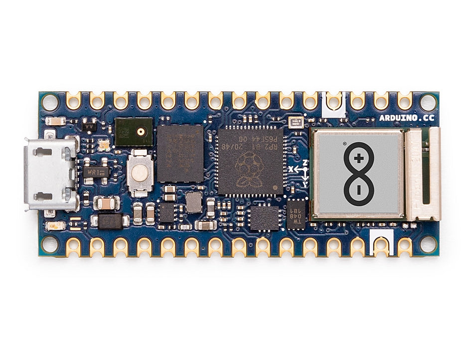
For full datasheet, photos, and dimensions see the Arduino Nano RP2040 Connect product page.
Highlights
Raspberry Pi RP2040 dual ARM Cortex‑M0+ at 133 MHz with 264 KB internal SRAM.
16 MB external QSPI flash.
U‑blox NINA‑W102 module providing 2.4 GHz Wi‑Fi b/g/n and Bluetooth 4.2 (BR/EDR + LE).
LSM6DSOX 6‑axis IMU and MP34DT06 PDM microphone.
Micro USB connector for power, programming, and a CDC REPL.
22 user I/O pins on the standard Nano headers —
TX/RX,D2–D13(digital),A0–A7(analog).
Pinout
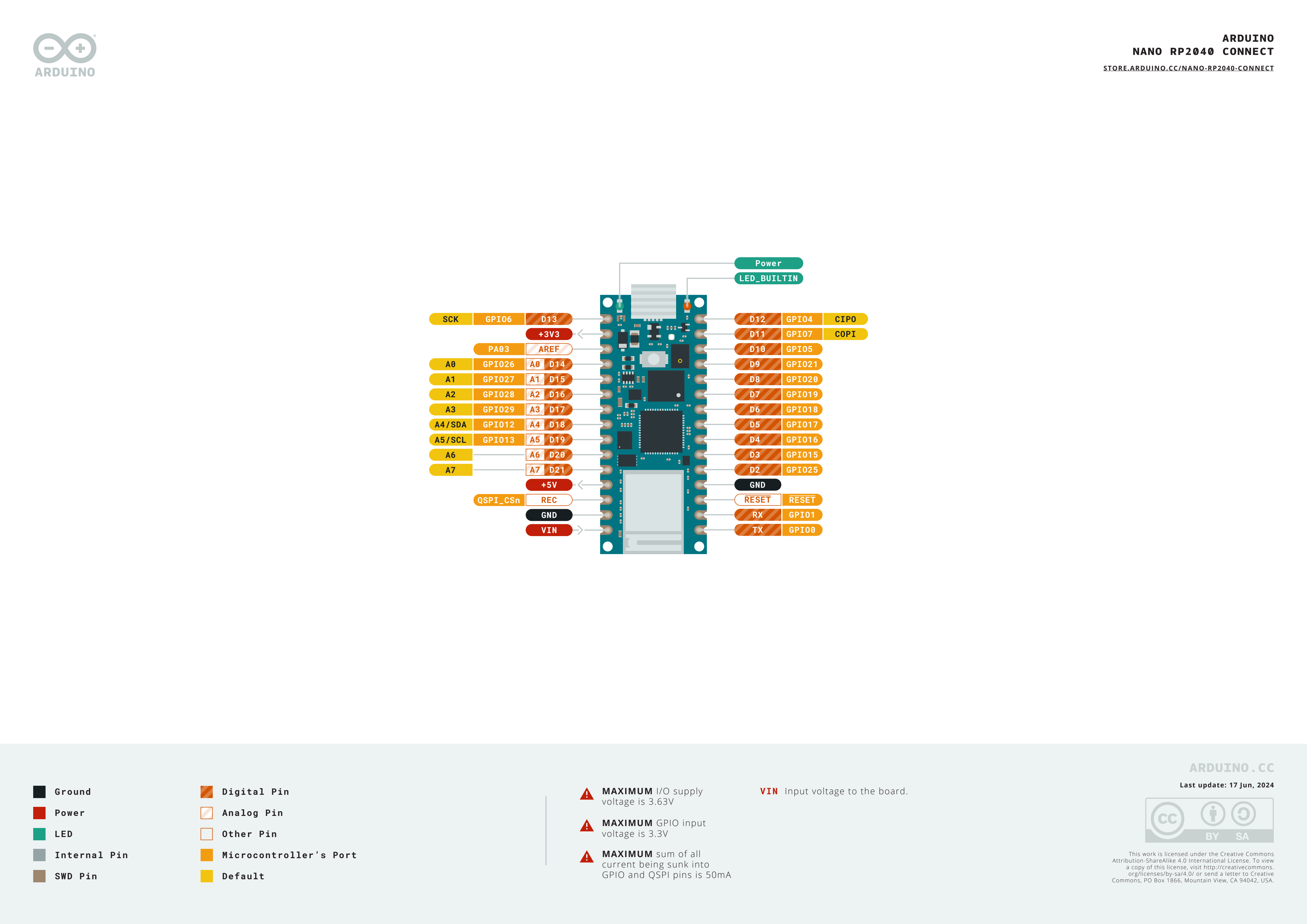
Pin reference
Pin name |
Reference |
Function |
|---|---|---|
TX |
3.3 V |
UART0 TX / SPI0 RX / I2C0 SDA / PWM0 A |
RX |
3.3 V |
UART0 RX / SPI0 CS / I2C0 SCL / PWM0 B |
D2 |
3.3 V |
SPI1 CS / UART1 RX / I2C0 SCL / PWM4 B |
D3 |
3.3 V |
SPI1 TX / UART0 RTS / I2C1 SCL / PWM7 B |
D4 |
3.3 V |
SPI0 RX / UART0 TX / I2C0 SDA / PWM0 A |
D5 |
3.3 V |
SPI0 CS / UART0 RX / I2C0 SCL / PWM0 B |
D6 |
3.3 V |
SPI0 SCK / UART0 CTS / I2C1 SDA / PWM1 A |
D7 |
3.3 V |
SPI0 TX / UART0 RTS / I2C1 SCL / PWM1 B |
D8 |
3.3 V |
SPI0 RX / UART1 TX / I2C0 SDA / PWM2 A |
D9 |
3.3 V |
SPI0 CS / UART1 RX / I2C0 SCL / PWM2 B |
D10 |
3.3 V |
SPI0 CS / UART1 RX / I2C0 SCL / PWM2 B |
D11 |
3.3 V |
SPI0 TX / UART1 RTS / I2C1 SCL / PWM3 B |
D12 |
3.3 V |
SPI0 RX / UART1 TX / I2C0 SDA / PWM2 A |
D13 |
3.3 V |
SPI0 SCK / UART1 CTS / I2C1 SDA / PWM3 A |
D14 / A0 |
3.3 V |
ADC / SPI1 SCK / UART1 CTS / I2C1 SDA / PWM5 A |
D15 / A1 |
3.3 V |
ADC / SPI1 TX / UART1 RTS / I2C1 SCL / PWM5 B |
D16 / A2 |
3.3 V |
ADC / SPI1 RX / UART0 TX / I2C0 SDA / PWM6 A |
D17 / A3 |
3.3 V |
ADC / SPI1 CS / UART0 RX / I2C0 SCL / PWM6 B |
D18 / A4 / SDA |
3.3 V |
ADC / I2C0 SDA / SPI1 RX / UART0 TX / PWM6 A |
D19 / A5 / SCL |
3.3 V |
ADC / I2C0 SCL / SPI1 CS / UART0 RX / PWM6 B |
D20 / A6 |
3.3 V |
ADC / GPIO |
D21 / A7 |
3.3 V |
ADC / GPIO |
RESET |
3.3 V |
press the on‑board RESET button or pull to GND to reset |
REC |
3.3 V |
BOOTSEL — pull high at power‑on to enter the RP2040 ROM bootloader |
LED_BUILTIN |
— |
Orange user LED on |
LED_RED |
— |
RGB LED red channel |
LED_GREEN |
— |
RGB LED green channel |
LED_BLUE |
— |
RGB LED blue channel |
Warning
The Nano RP2040 Connect’s I/O pins are 3.3 V only — they are not 5 V tolerant. Driving 5 V into them will damage the RP2040.
Power pins
VIN — 4 – 20 V input. Powers the board through the on‑board switching regulator. Also fed via a diode from the USB 5 V rail, so USB and
VINcan be present at the same time without back‑driving each other.+5V — unconnected by default.
+3V3 — 3.3 V regulator output.
AREF — analog reference pin. Not wired to the RP2040 on this board — the ADC is always referenced to 3.3 V.
GND — common ground.
The Nano RP2040 Connect can be powered through either path:
Micro USB — supplies 5 V to the on‑board regulator.
VIN pin — drive a regulated 4 – 20 V supply.
Note
A solder jumper on the bottom of the board bridges +5V to
the USB 5 V rail. Close it to make the +5V header pin
actually carry 5 V.
Note
A normally‑closed solder jumper on the output of the on‑board
4–20 V switching regulator can be cut to disable the regulator,
so the board can be powered directly from an external 3.3 V
supply on +3V3.
Recovery and debug pins
RESET — both an exposed pad and a momentary RESET button on the top of the board, tied to the RP2040’s NRST line. Pull to GND or press the button to reset.
REC — exposed pad. Holding
REChigh at power‑on (or while pressing RESET) puts the RP2040 into its ROM bootloader; the board re‑enumerates as a USB mass‑storage drive namedRPI-RP2and accepts a.uf2firmware image.
The Nano RP2040 Connect uses Arduino’s standard double‑tap reset to enter Arduino’s bootloader. Quickly press the RESET button twice — the board re‑enumerates over USB as a UF2 device and OpenMV IDE can flash a new firmware image.
The RP2040’s SWD signals are exposed on plated pads on the back of the board, just below the NINA module. All debug signals are 3.3 V referenced.
Onboard peripherals
LEDs
The Nano RP2040 Connect has a user RGB LED — driven through the
silkscreened LED_RED, LED_GREEN, and LED_BLUE channels
— plus a separate orange LED_BUILTIN on D13. All four are
software‑controllable through machine.LED:
from machine import LED

LED("LED_RED").on()
LED("LED_GREEN").on()
LED("LED_BLUE").on()
LED("LED_BUILTIN").on()
A separate green power LED on the board lights whenever the +3.3 V rail is up and is not user‑controllable.
Camera sensor
The OpenMV firmware on the Nano RP2040 Connect supports the OmniVision OV7670 parallel CMOS sensor. The board has no on‑board image sensor — wire an OV7670 module to the silkscreened header pins listed below and drive it through the csi — camera sensors module:
import csi

cam = csi.CSI()
cam.reset()
cam.pixformat(csi.RGB565)
cam.framesize(csi.QVGA)
cam.snapshot(time=2000)       # let auto‑exposure settle

while True:
    img = cam.snapshot()
Note
The OV7670 takes 14 pins. The firmware wires them as follows:
Sensor signal |
Nano RP2040 pin |
|---|---|
D0 |
|
D1 |
|
D2 |
|
D3 |
|
D4 |
|
D5 |
|
D6 |
|
D7 |
|
HSYNC |
|
VSYNC |
|
PXCLK |
|
MXCLK |
|
POWER |
|
RESET |
|
SCL |
|
SDA |
|
The OV7670’s I²C control bus is shared with the on‑board IMU
and ATECC608A on I²C 0. The sensor sits at 7‑bit address
0x21 — user devices on bus 0 must also avoid this address
when the camera is wired up.
IMU
The on‑board LSM6DSOX 6‑axis accelerometer + gyroscope sits on
I2C0. The rp2 port’s
machine.I2C(0) defaults to a different pin set, so pass the
silkscreened SDA/SCL pads explicitly. Use the frozen
lsm6dsox.LSM6DSOX driver:
import time
from machine import I2C, Pin
from lsm6dsox import LSM6DSOX

bus = I2C(0, scl=Pin("SCL"), sda=Pin("SDA"))
imu = LSM6DSOX(bus)

while True:
    print(imu.accel())     # (x, y, z) in g
    print(imu.gyro())      # (x, y, z) in deg/s
    time.sleep_ms(100)
Microphone
The on‑board MP34DT06 PDM microphone is captured through audio — Audio Module using one of the RP2040’s PIO blocks:
import audio
from ulab import numpy as np

def loudness(pcmbuf):
    samples = np.array(np.frombuffer(pcmbuf, dtype=np.int16), dtype=np.float)
    rms = np.sqrt(np.mean(samples ** 2))
    if rms > 10000:
        print("Loud!", int(rms))

audio.init(channels=1, frequency=16000, gain_db=24)
audio.start_streaming(loudness)

while True:
    pass
Wi‑Fi
The on‑board NINA‑W102 module is exposed via network — network configuration as a station interface:
import network, time

wlan = network.WLAN(network.STA_IF)
wlan.active(True)
wlan.connect("ssid", "password")
while not wlan.isconnected():
    time.sleep(1)
print("Wi‑Fi IP:", wlan.ipconfig("addr4")[0])
Bluetooth
The same NINA module also exposes Bluetooth 4.2 LE. Use aioble — Async BLE for asyncio‑friendly BLE — for example, advertise as a peripheral and wait for a central to connect:
import asyncio
import aioble

async def run():
    while True:
        conn = await aioble.advertise(250_000, name="Nano-RP2040")
        print("Connected:", conn.device)
        await conn.disconnected()

asyncio.run(run())
Bus reference
GPIO
Use machine.Pin to read or drive any of the silkscreened pins. Outputs are 3.3 V CMOS, 50 mA total sink across all GPIOs.
from machine import Pin

out = Pin("D2", Pin.OUT)
out.on()
out.off()
out.value(1)

inp = Pin("D3", Pin.IN, Pin.PULL_UP)
print(inp.value())
Any input pin can also fire an interrupt on edge transitions:
def handler(pin):
    print("triggered:", pin)

Pin("D3", Pin.IN, Pin.PULL_UP).irq(
    handler, Pin.IRQ_FALLING | Pin.IRQ_RISING,
)
UART
Bus |
TX |
RX |
|---|---|---|
UART0 |
TX |
RX |
Use the silkscreen names TX/RX with machine.UART:
from machine import UART

uart = UART(0, baudrate=115200)
uart.write("hello")
uart.read(5)
Note
machine.UART(1) exists but is reserved for the on‑board
NINA‑W102 module (the BLE link); don’t use it directly.
I²C
Bus |
SDA |
SCL |
|---|---|---|
I2C0 |
|
|
I2C1 |
|
|
Both buses need their pins passed explicitly to
machine.I2C:
from machine import I2C, Pin

bus0 = I2C(0, scl=Pin("SCL"), sda=Pin("SDA"), freq=400_000)
bus0.scan()

bus1 = I2C(1, scl=Pin("A1"),  sda=Pin("A0"),  freq=400_000)
bus1.scan()
Note
Two on-board chips share bus 0 — user devices on this bus must avoid their addresses:
0x6A— LSM6DSOX IMU0x60— ATECC608A‑MAHDA‑T
Using A0/A1 as I²C consumes them for the bus, so they
can’t simultaneously be ADC inputs.
Note
The SDA / SCL pads (bus 0) have on‑board pull‑up
resistors to 3.3 V, so no external pull‑ups are needed for
devices on that bus. A0 / A1 (bus 1) do not — add
external pull‑ups when using bus 1.
The same hardware can also be used in target (slave) mode through machine.I2CTarget to expose a memory region to another I²C controller:
from machine import I2CTarget

buf = bytearray(32)
target = I2CTarget(0, addr=0x42, mem=buf)
SPI
Bus |
MOSI |
MISO |
SCK |
CS |
|---|---|---|---|---|
SPI0 |
D11 |
D12 |
D13 |
D10 |
The rp2 port doesn’t pre-configure SPI0’s pins on this board, so pass the silkscreened pads explicitly when creating the bus:
from machine import SPI, Pin

spi = SPI(0, baudrate=10_000_000,
          sck=Pin("D13"), mosi=Pin("D11"), miso=Pin("D12"))
cs = Pin("D10", Pin.OUT, value=1)   # CS is not driven by the SPI peripheral

cs.value(0)
spi.write(b"hello")
cs.value(1)
Note
D13 doubles as the orange LED_BUILTIN — driving SPI on
this bus will blink the LED in time with the bus clock.
Note
machine.SPI(1) exists but is reserved for the on-board
NINA‑W102 module (the Wi-Fi/BLE SPI link); don’t use it directly.
ADC
The RP2040 has four 12‑bit ADC channels exposed on A0–A3, all
3.3 V referenced — read_u16 returns 0–65535 across 0–3.3 V
at the pin. The board’s AREF pin is not wired, so the reference
is always 3.3 V:
from machine import ADC
import time

adc = ADC("A0")
while True:
    voltage = adc.read_u16() * 3.3 / 65535
    print(voltage)
    time.sleep_ms(100)
PWM
Pin |
Slice / channel |
|---|---|
TX |
PWM0 A |
RX |
PWM0 B |
D2 |
PWM4 B |
D3 |
PWM7 B |
D4 |
PWM0 A |
D5 |
PWM0 B |
D6 |
PWM1 A |
D7 |
PWM1 B |
D8 |
PWM2 A |
D9 |
PWM2 B |
D10 |
PWM2 B |
D11 |
PWM3 B |
D12 |
PWM2 A |
D13 |
PWM3 A |
D14 / A0 |
PWM5 A |
D15 / A1 |
PWM5 B |
D16 / A2 |
PWM6 A |
D17 / A3 |
PWM6 B |
D18 / A4 / SDA |
PWM6 A |
D19 / A5 / SCL |
PWM6 B |
Drive any of them via machine.PWM:
from machine import Pin, PWM

pwm = PWM(Pin("D3"), freq=1_000, duty_u16=32768)
Note
Several pins share PWM slice channels:
PWM0 A is on
TXandD4.PWM0 B is on
RXandD5.PWM2 A is on
D8andD12.PWM2 B is on
D9andD10.PWM6 A is on
D16/A2andD18/A4/SDA.PWM6 B is on
D17/A3andD19/A5/SCL.
Pick one consumer per slice channel. Channels A and B inside the same slice share their period (frequency) but each has its own duty cycle.
Software bit‑banged buses
machine.SoftI2C and machine.SoftSPI work on any GPIO if you need an extra bus.
Thermal sensor (off‑board)
The firmware includes the fir — thermal sensor driver (fir == far infrared) driver for an
externally wired AMG8833 8×8 thermal imager. Connect the
module to the I²C bus listed below, then read frames with
fir.init() + fir.snapshot():
import time
import image
import fir

fir.init()                          # auto‑detects the sensor
clock = time.clock()

while True:
    clock.tick()
    try:
        img = fir.snapshot(x_scale=5, y_scale=5,
                           color_palette=image.PALETTE_IRONBOW,
                           hint=image.BICUBIC,
                           copy_to_fb=True)
    except OSError:
        continue
    print(clock.fps())
The fir driver only talks to the sensor over I²C 0 — wire
the module to the silkscreened SCL / SDA pads. The
sensor’s 7‑bit address (0x69) must not be used by any other
device on that bus.
Timing
time
The time module covers blocking delays, monotonic ticks, and
elapsed‑time measurement:
import time

time.sleep(1)              # seconds
time.sleep_ms(500)
time.sleep_us(10)

start = time.ticks_ms()
# ...do work...
elapsed = time.ticks_diff(time.ticks_ms(), start)
Virtual timers
machine.Timer schedules periodic or one‑shot
callbacks without consuming a hardware timer slot. Pass -1 as the
id to use a virtual (software) timer:
from machine import Timer

one_shot = Timer(-1)
one_shot.init(period=5_000, mode=Timer.ONE_SHOT,
              callback=lambda t: print("once"))

periodic = Timer(-1)
periodic.init(period=2_000, mode=Timer.PERIODIC,
              callback=lambda t: print("tick"))
Period values are in milliseconds. Call deinit()
to stop and release the slot.
Real‑time clock
machine.RTC keeps wall‑clock time across resets. The RP2040’s RTC is tied to the on‑chip oscillator and does not survive full power loss — set the time on every cold boot if it matters to your application:
from machine import RTC

rtc = RTC()
rtc.datetime((2026, 4, 30, 4, 12, 0, 0, 0))   # Y, M, D, weekday, h, m, s, subsec
print(rtc.datetime())
Watchdog
machine.WDT resets the board if the application hangs. Once started it can’t be stopped or reconfigured — feed it periodically inside your main loop:
from machine import WDT

wdt = WDT(timeout=5_000)   # 5 second window
while True:
    # ...do work...
    wdt.feed()
Boot and runtime info
Firmware update (UF2)
The Nano RP2040 Connect uses Arduino’s standard double‑tap reset to enter Arduino’s bootloader. Quickly press the reset button twice — the board re‑enumerates over USB as a UF2 device and OpenMV IDE can flash a new firmware image.
A running script can re‑enter the bootloader on demand by calling
machine.bootloader():
import machine

machine.bootloader()
Filesystem and boot order
The Nano RP2040 Connect firmware mounts a single filesystem on boot:
Internal flash — always mounted at
/flashand used as the working directory. Holdsmain.pyandREADME.txtby default; created on the very first boot.
After mounting, the interpreter then runs scripts from /flash:
boot.pyis executed on every soft reset.main.pyis executed only on cold boot, immediately afterboot.py.
The default main.py shipped on a freshly flashed board just
blinks the user RGB LED’s blue channel as a heartbeat (two
short pulses, short gap), so you can tell the firmware booted
cleanly without any host attached.
When connected over USB, /flash enumerates as a USB mass‑storage
drive on the host, letting you edit boot.py, main.py, and any
other files directly. Eject the drive before resetting the board
so the host flushes its cached writes.
Note
Because the OS treats the drive as a passive block device, files created or modified by code running on the camera will not show up until the host re‑mounts the drive. If both the OS and the camera write the same filesystem at the same time, the OS will win and overwrite changes made by the camera. Use the SD card for any data the script writes back, and remount before reading those files from the host.
Note
The user RGB LED’s red channel may briefly light up while the host is reading from or writing to the USB mass‑storage drive — this is a firmware‑driven activity indicator, not a fault.
Storage sizes
The Nano RP2040 Connect ships with:
/flash— 14 MB FAT filesystem, read/write.
The Nano RP2040 build does not include a ROMFS; ship Python
modules and ML models on /flash directly.
Software libraries
See the library index for the full list of modules — including which ones are unique to the Nano RP2040 Connect build.