OpenMV AE3
The OpenMV AE3 is built around the Alif Ensemble E3 — a dual ARM Cortex‑M55 SoC (400 MHz HP core + 160 MHz HE core) with two on‑chip NPUs (400 MHz / 204 GOPS HP NPU + 160 MHz / 46 GOPS HE NPU). The board pairs the NPUs with the PAG7936 1 MP global‑shutter sensor, USB‑C high‑speed, Wi‑Fi, Bluetooth 5.1, an LSM6DSM IMU, a microphone, and an 8×8 VL53L8CX time‑of‑flight rangefinder, all on a 30 × 30 mm board.
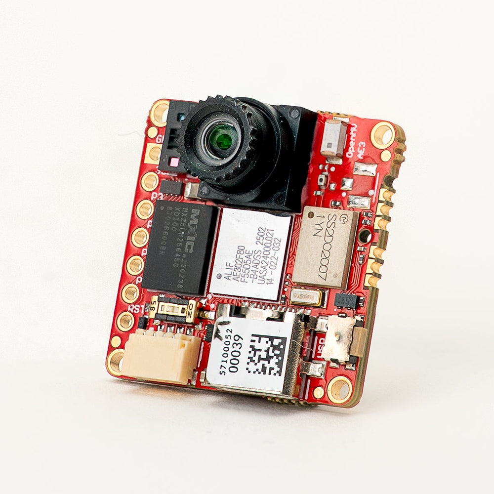
For full datasheet, photos, and dimensions see the OpenMV AE3 product page.
Highlights
Alif Ensemble E3 — dual ARM Cortex‑M55 with Helium 128‑bit SIMD, 400 MHz HP core + 160 MHz HE core (~640 / ~256 DMIPS, CoreMark 1748 / 752).
Dual NPUs: 400 MHz / 204 GOPS HP NPU + 160 MHz / 46 GOPS HE NPU for AI/ML — runs YOLO object detection alongside other workloads.
Hardware 2D GPU for scaling.
13.5 MB internal SRAM plus 5.5 MB on‑chip MRAM and 32 MB external octal flash (100 MHz 8‑bit DDR, 200 MB/s read).
4 KB backup RAM with the on‑chip RTC.
PAG7936 1 MP color global‑shutter sensor.
Onboard IMU (LSM6DSM accelerometer + gyroscope), microphone, and VL53L8CX 8×8 time‑of‑flight sensor (up to 4 m).
High‑speed USB‑C (480 Mb/s) with EMI filtering and TVS protection, Wi‑Fi a/b/g/n + Bluetooth 5.1 (chip antenna or U.FL option).
10 user I/O pins — P0–P3 on the side headers, P4–P5 on the Qwiic connector, and P6–P9 on the B2B header on the back. Additional debug and recovery lines are also routed to the B2B header.
All pins 3.3 V output / 3.3 V tolerant, 25 mA per pin, interrupt‑capable. ADC inputs are 1.8 V referenced.
User RGB LED, user button, recovery switch, Qwiic connector.
80 µA deep sleep at 3.3 V (24 mA idle, 50–60 mA active).
Warning
The AE3’s I/O pins are not 5 V tolerant. Do not connect the device directly to a 5 V MCU like the Arduino Mega — use a level shifter for any 5 V signal.
Pinout
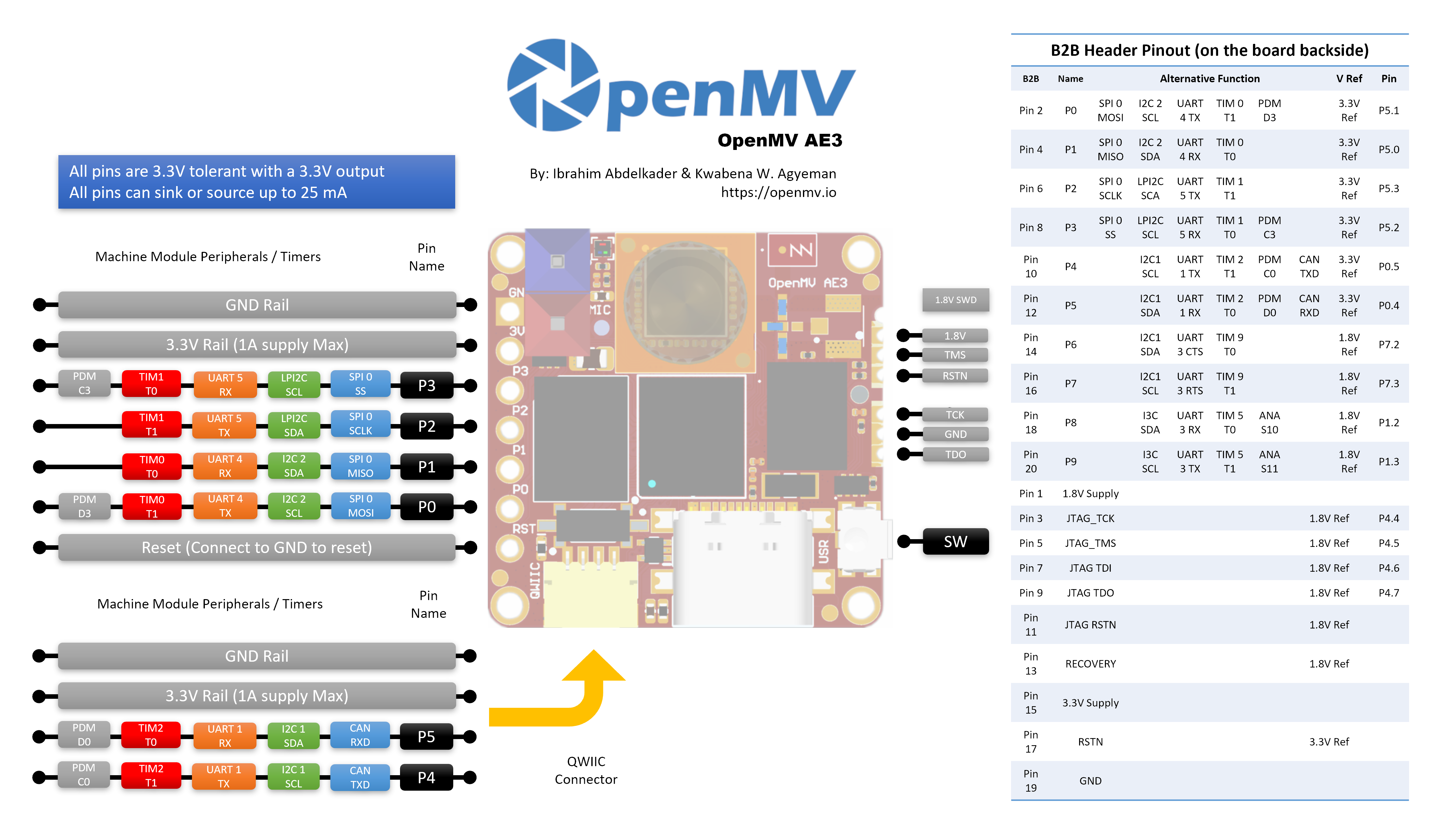
Pin reference
The AE3 exposes 10 user pins on the side headers (P0–P9). Additional signals — including JTAG and the recovery line — are routed to a B2B (board‑to‑board) header on the back of the board for shields and carrier boards.
Pin name |
Reference |
Function |
|---|---|---|
P0 |
3.3 V |
SPI0 MOSI / I2C2 SCL / UART4 TX / TIM0 T1 / PDM D3 |
P1 |
3.3 V |
SPI0 MISO / I2C2 SDA / UART4 RX / TIM0 T0 |
P2 |
3.3 V |
SPI0 SCLK / LPI2C SDA / UART5 TX / TIM1 T1 |
P3 |
3.3 V |
SPI0 SS / LPI2C SCL / UART5 RX / TIM1 T0 / PDM C3 |
P4 |
3.3 V |
I2C1 SCL / UART1 TX / TIM2 T1 / PDM C0 / CAN TX |
P5 |
3.3 V |
I2C1 SDA / UART1 RX / TIM2 T0 / PDM D0 / CAN RX |
P6 |
1.8 V |
I2C1 SDA / UART3 CTS / TIM9 T0 (B2B only) |
P7 |
1.8 V |
I2C1 SCL / UART3 RTS / TIM9 T1 (B2B only) |
P8 |
1.8 V |
I3C SDA / UART3 RX / TIM5 T0 / ADC ch S10 (B2B only) |
P9 |
1.8 V |
I3C SCL / UART3 TX / TIM5 T1 / ADC ch S11 (B2B only) |
P10 |
1.8 V |
GPIO / JTAG TCK (B2B only) |
P11 |
1.8 V |
GPIO / JTAG TDO (B2B only) |
P13 |
1.8 V |
GPIO / JTAG TMS (B2B only) |
P14 |
1.8 V |
GPIO / JTAG TDI (B2B only) |
RESET |
3.3 V |
pull to GND to reset the board |
SW |
3.3 V |
user button (active low) |
LED_RED |
3.3 V |
RGB LED red channel (active low) |
LED_GREEN |
3.3 V |
RGB LED green channel (active low) |
LED_BLUE |
3.3 V |
RGB LED blue channel (active low) |
Note
P0–P5 are on the side headers (3.3 V referenced); P6–P9 are exposed only on the B2B header on the back of the board and are 1.8 V referenced. Driving 3.3 V into a 1.8 V‑referenced pin will damage the SoC — make sure any signal connected to the B2B header is at 1.8 V.
Power pins
3.3V — the AE3’s main power rail. The same 3.3 V rail is exposed on the GPIO header solder pads, the Qwiic connector, and the B2B header on the back of the board.
1.8V — exposed on the B2B header as an output only. Use it to power 1.8 V‑logic peripherals on a B2B carrier; do not drive it from outside the board.
GND — common ground.
The AE3 has no VIN pin and no LiPo charger. It can be powered through any of three paths:
USB‑C — the on‑board regulator drops 5 V from USB to 3.3 V and injects that onto the 3.3 V rail.
Qwiic connector — drive a regulated 3.3 V supply into the Qwiic header to power the board from a Qwiic module.
GPIO header / B2B 3.3 V pads — drive a regulated 3.3 V supply into any of the 3.3 V pads on the I/O header or the B2B connector.
The USB regulator feeds the rail through an ideal diode, so external 3.3 V supplies on the Qwiic / GPIO / B2B side can power the board even while USB is still attached without back‑driving the USB regulator.
Tip
Use the battery life estimator to model how long the AE3 will run on a battery for a given active / deep-sleep duty cycle.
Recovery and debug pins
RESET — pull to GND to reset the board. Releasing it lets the SoC start up normally.
There is a recovery switch on the front (camera‑side) face of the board, in the bottom‑left corner. When enabled, it forces the AE3’s SE UART out over USB so OpenMV IDE can reflash the on‑board bootloader. The same recovery mode can be triggered remotely by pulling the RECOVERY pin on the B2B connector low.
The AE3 supports both SWD and full JTAG debugging:
The 1.8 V SWD header on the side of the board is for a Tag-Connect ECV3-06-CTX cable and breaks out the four SWD signals (TCK / TMS / TDO / RSTN) plus GND.
The B2B header on the back of the board exposes the same debug pins (P10 = TCK, P11 = TDO, P13 = TMS, P14 = TDI) plus the system RSTN and a separate JTAG RSTN. These pins can be used for either SWD (TCK + TMS) or full JTAG; the JTAG RSTN line is only needed in full-JTAG mode.
All debug signals are 1.8 V referenced — make sure your debug adapter is configured for 1.8 V logic before connecting.
Onboard peripherals
LEDs
The AE3 has a single user RGB LED, software‑controllable through machine.LED:
from machine import LED

LED("LED_RED").on()
LED("LED_GREEN").on()
LED("LED_BLUE").on()
Camera sensor
The PAG7936 is driven through the csi — camera sensors module:
import csi

cam = csi.CSI()
cam.reset()
cam.pixformat(csi.RGB565)
cam.framesize(csi.HD)         # 1280×800
cam.snapshot(time=2000)       # let auto‑exposure settle

while True:
    img = cam.snapshot()
The PAG7936 supports triggered mode — pixel integration lines up
exactly with each csi.CSI.snapshot call rather than the
free-running frame clock, useful for syncing capture to an
external event or another sensor. Enable it through
csi.CSI.ioctl with csi.IOCTL_SET_TRIGGERED_MODE. Frame rate
drops to roughly half of free-running mode because the readout no
longer pipelines with the next frame’s integration:
cam.ioctl(csi.IOCTL_SET_TRIGGERED_MODE, True)
NPU
The AE3’s two on‑chip NPUs (400 MHz / 204 GOPS HP NPU + 160 MHz /
46 GOPS HE NPU) are exposed through the ml — Machine Learning module.
Models stored on the read‑only /rom filesystem load directly from
flash without copying to RAM, so even large detectors fit comfortably
alongside the live framebuffer. Run a YOLOv8 detector on every frame
and draw the predictions on top of the live image:
import csi
import time
import ml
from ml.postprocessing.ultralytics import YoloV8

# Initialize the sensor.
csi0 = csi.CSI()
csi0.reset()
csi0.pixformat(csi.RGB565)
csi0.framesize(csi.VGA)

# Load YOLO V8 model from ROM FS.
model = ml.Model("/rom/yolov8n_192.tflite", postprocess=YoloV8(threshold=0.4))
print(model)

# Visualization parameters.
n = len(model.labels)
model_class_colors = [
    (int(255 * i // n), int(255 * (n - i - 1) // n), 255)
    for i in range(n)
]

clock = time.clock()
while True:
    clock.tick()
    img = csi0.snapshot()

    # boxes is a list of list per class of ((x, y, w, h), score) tuples
    boxes = model.predict([img])

    # Draw bounding boxes around the detected objects
    for i, class_detections in enumerate(boxes):
        rects = [r for r, score in class_detections]
        labels = [model.labels[i] for j in range(len(rects))]
        colors = [model_class_colors[i] for j in range(len(rects))]
        ml.utils.draw_predictions(img, rects, labels, colors, format=None)

    print(clock.fps(), "fps")
HE core
The AE3 packages two Cortex‑M55 cores in one MCU: the high-performance (HP) core that runs the main MicroPython instance, the camera, the HP NPU, USB, and so on; and the high-efficiency (HE) core that sits at much lower power and boots into a small MicroPython instance of its own. Both cores share an Open-AMP / RPMsg message bus, so the HP core can dispatch Python functions to the HE core, get results back, and keep the two halves decoupled.
The simplest entry point is the @openamp.async_remote
decorator. It marshals a Python function, ships it to the HE
core, and the HE core runs it as an asyncio task. After
registering tasks, instantiate openamp.RemoteProc with the
HE firmware’s flash address and call rproc.start() to boot
the second core. With no callback, the decorated function’s
print() output is forwarded over the default endpoint to
the HP core’s stdout — handy for a “hello world”:
import time
import openamp

@openamp.async_remote
async def task1(ept):
    import asyncio
    while True:
        print("Hello from the HE core!")
        await asyncio.sleep(1)

# Boot the HE core. This runs the registered tasks.
rproc = openamp.RemoteProc(0x80320000)
rproc.start()

while True:
    print("Hello from the HP core!")
    time.sleep(1)
For bidirectional messaging, pass a callback to the decorator.
The callback runs on the HP core whenever the HE task calls
ept.send():
import time
import openamp

def task_callback(src_addr, data):
    print("HP received:", data.decode())

@openamp.async_remote(task_callback)
async def task1(ept):
    import asyncio
    count = 0
    while True:
        ept.send(f"count = {count}")
        count += 1
        await asyncio.sleep(1)

rproc = openamp.RemoteProc(0x80320000)
rproc.start()

while True:
    time.sleep(1)
The HE core has its own HE NPU (160 MHz, 46 GOPS), so it
can run a second ML model in parallel with whatever the HP
core’s HP NPU is busy with. A useful split is to put a small
always-on trigger / classifier model on the HE side and let
the HP core react only when something interesting is flagged —
keyword spotting from the on-board microphone is a good fit
because it’s continuous, low-bandwidth, and the HE core stays
at much lower power than HP. The frozen ml.apps.MicroSpeech
helper recognizes “Yes” and “No” out of the box — say the words
loudly and clearly into the on-board mic to trigger detection:
import time
import openamp

def task_callback(src_addr, data):
    print("Heard:", data.decode())

@openamp.async_remote(task_callback)
async def task1(ept):
    from ml.apps import MicroSpeech
    speech = MicroSpeech(gain_db=24)
    while True:
        label, scores = speech.listen(timeout=0, threshold=0.70)
        if label:
            ept.send(label)

rproc = openamp.RemoteProc(0x80320000)
rproc.start()

while True:
    time.sleep(1)
For a richer split, run BlazeFace on the HP NPU while the HE core handles keyword spotting in the background — the HP loop overlays the most recent heard keyword on the camera frame:
import csi
import time
import openamp
import ml
from ml.postprocessing.mediapipe import BlazeFace

label = None
label_ticks = 0
LABEL_HOLD_MS = 2000

def task_callback(src_addr, data):
    global label, label_ticks
    label = data.decode()
    label_ticks = time.ticks_ms()

@openamp.async_remote(task_callback)
async def task1(ept):
    from ml.apps import MicroSpeech
    speech = MicroSpeech(gain_db=24)
    while True:
        l, scores = speech.listen(timeout=0, threshold=0.70)
        if l:
            ept.send(l)

# Start the HE core before initializing the camera on the HP core.
rproc = openamp.RemoteProc(0x80320000)
rproc.start()

csi0 = csi.CSI()
csi0.reset()
csi0.pixformat(csi.RGB565)
csi0.framesize(csi.VGA)
csi0.window((400, 400))

model = ml.Model("/rom/blazeface_front_128.tflite",
                 postprocess=BlazeFace(threshold=0.4))

clock = time.clock()
while True:
    clock.tick()
    img = csi0.snapshot()
    for r, score, keypoints in model.predict([img]):
        ml.utils.draw_predictions(img, [r], ("face",),
                                  ((0, 0, 255),), format=None)
        ml.utils.draw_keypoints(img, keypoints, color=(255, 0, 0))
    if label is not None:
        if time.ticks_diff(time.ticks_ms(), label_ticks) < LABEL_HOLD_MS:
            img.draw_string((4, 4), f"Heard: {label}",
                            color=(255, 0, 0), scale=2)
        else:
            label = None
    print(clock.fps(), "fps")
The HE core is well suited to always-on or low-rate workloads that you don’t want competing with the camera/NPU pipeline on the HP side — small ML inference, lightweight DSP on microphone or IMU data, and similar background jobs.
A few constraints to keep in mind:
Stick to the microphone and IMU when driving peripherals from the HE core — those are what the HE side is designed for. Each peripheral can only be owned by one core at a time, so pick HP or HE for it and stick with that for the lifetime of the script.
Each
@openamp.async_remotetask body must marshal to under 500 bytes of mpy bytecode — keep the function small and factor heavier logic into separate library modules that get frozen into the firmware.Imports inside the dispatched function only see modules that exist on the HE core’s filesystem. The HE core has its own
/romROMFS — separate from the HP core’s/rom— so modules and ML models you want available on HE need to be baked into the HE-side ROMFS image, not the HP one.
Microphone
The on‑board mic is captured through audio — Audio Module. Each
buffer arrives as a signed‑16‑bit PCM bytearray, which makes it
trivial to feed into ulab/numpy for
quick DSP. A simple loudness detector — print whenever the RMS volume
crosses a threshold:
import audio
from ulab import numpy as np

def loudness(pcmbuf):
    samples = np.array(np.frombuffer(pcmbuf, dtype=np.int16), dtype=np.float)
    rms = np.sqrt(np.mean(samples ** 2))
    if rms > 10000:
        print("Loud!", int(rms))

audio.init(channels=1, frequency=16000, gain_db=24)
audio.start_streaming(loudness)

while True:
    pass
IMU
The on‑board LSM6DSM accelerometer + gyroscope is exposed through imu — imu sensor:
import imu
import time

while True:
    print(imu.acceleration_mg())   # (x, y, z) in milli‑g
    print(imu.angular_rate_mdps()) # (x, y, z) in milli‑deg/s
    time.sleep_ms(100)
Time‑of‑flight sensor
The AE3 carries a VL53L8CX 8×8 multi‑zone time‑of‑flight sensor
that returns up to 64 distance readings per frame, with a maximum
range of ~4 m. It’s exposed through the tof — time-of-flight sensor driver
module — call tof.init() to start the sensor and
tof.read_depth() to grab a depth frame as a flat list of
millimetre readings (one per zone):
import tof

tof.init()
while True:
    depth, depth_min, depth_max = tof.read_depth()
    print("min:", depth_min, "mm  max:", depth_max, "mm")
The depth array can also be drawn over a colour frame from the main
sensor — tof.draw_depth() paints it onto an existing
image.Image, while tof.snapshot() returns a freshly
rendered depth image:
import image
import tof
import csi

# Bring up the VL53L8CX time-of-flight sensor.
tof.init()

# Configure the main camera at VGA RGB565.
cam = csi.CSI()
cam.reset()
cam.pixformat(csi.RGB565)
cam.framesize(csi.VGA)

# Off-screen framebuffer used to compose the camera frame and the
# up-scaled depth heat-map side by side before pushing the result
# back to the live preview.
b = image.Image(640, 480, image.RGB565)

while True:
    # Grab a colour frame from the main camera.
    img = cam.snapshot()

    try:
        # Capture TOF data [depth map, min distance, max distance].
        # vflip / hmirror align the ToF orientation with the camera.
        depth, dmin, dmax = tof.read_depth(vflip=True, hmirror=True)

        # Zones with no return read back as 0.0 — clamp them to the
        # frame's max distance so the colour palette doesn't show
        # them as "closest".
        for i in range(0, len(depth)):
            if depth[i] == 0.0:
                depth[i] = dmax

    except RuntimeError:
        # The sensor occasionally faults on a frame; reset and skip.
        tof.reset()
        continue

    # Draw the camera frame into the left half of the framebuffer,
    # scaled to 60% so it leaves room for the depth heat-map on
    # the right.
    b.draw_image(img, x=0, y=64+8, x_scale=0.6, hint=image.BILINEAR)

    # Up-sample the 8x8 depth array 30x with bicubic smoothing and
    # blend it into the right half using the depth palette.
    # scale=(0, 400) maps 0-400 mm to the full palette range.
    tof.draw_depth(b, depth, x=320+64+16, y=64+8, alpha=255,
                   hint=image.BICUBIC, x_scale=30, y_scale=30,
                   scale=(0, 400), color_palette=image.PALETTE_DEPTH)

    # Copy the composed framebuffer back into the live preview so
    # OpenMV IDE shows both panels.
    img.set(b)
Wi‑Fi
The on‑board CYW43439 is exposed via network — network configuration as a
station interface. After connecting, ipconfig("addr4") returns the
(ip, netmask) pair:
import network, time

wlan = network.WLAN(network.STA_IF)
wlan.active(True)
wlan.connect("ssid", "password")
while not wlan.isconnected():
    time.sleep(1)
print("Wi‑Fi IP:", wlan.ipconfig("addr4")[0])
Bluetooth
The same CYW43439 also exposes Bluetooth 5.1. Use aioble — Async BLE for asyncio‑friendly BLE — for example, advertise as a peripheral and wait for a central to connect:
import asyncio
import aioble

async def run():
    while True:
        conn = await aioble.advertise(250_000, name="OpenMV-AE3")
        print("Connected:", conn.device)
        await conn.disconnected()

asyncio.run(run())
Bus reference
GPIO
Use machine.Pin to read or drive any of the silkscreened pins. Outputs are 3.3 V CMOS and can sink/source up to 25 mA per pin.
from machine import Pin

out = Pin("P0", Pin.OUT)
out.on()
out.off()
out.value(1)

inp = Pin("P1", Pin.IN, Pin.PULL_UP)
print(inp.value())
Any input pin can also fire an interrupt on edge transitions:
def handler(pin):
    print("triggered:", pin)

Pin("P1", Pin.IN, Pin.PULL_UP).irq(
    handler, Pin.IRQ_FALLING | Pin.IRQ_RISING,
)
UART
Bus |
TX |
RX |
RTS |
CTS |
|---|---|---|---|---|
UART1 |
P4 |
P5 |
— |
— |
UART3 |
P9 |
P8 |
P7 |
P6 |
UART4 |
P0 |
P1 |
— |
— |
UART5 |
P2 |
P3 |
— |
— |
from machine import UART

uart = UART(1, baudrate=115200)
uart.write("hello")
uart.read(5)
UART3 is the only bus with hardware flow control. Because P6–P9 sit on the B2B header and are 1.8 V referenced, UART3 only works through a level shifter or a B2B carrier — don’t connect 3.3 V logic to it directly.
I²C
Bus |
SCL |
SDA |
|---|---|---|
I2C1 |
P4 |
P5 |
I2C2 |
P0 |
P1 |
LPI2C |
P3 |
P2 |
from machine import I2C

i2c = I2C(1, freq=400_000)
i2c.scan()
i2c.writeto(0x76, b"hi")
The on‑board Qwiic connector breaks out I2C2 at 3.3 V.
I2C1 and I2C2 can also be used in target (slave) mode through
machine.I2CTarget to expose a memory region
to another I²C controller:
from machine import I2CTarget

buf = bytearray(32)
target = I2CTarget(1, addr=0x42, mem=buf)
Note
The LPI2C peripheral is not exposed in firmware. It would only
support target (slave) mode if exposed, and I2C1 and
I2C2 already cover both controller and target operation.
SPI
Bus |
MOSI |
MISO |
SCK |
CS |
|---|---|---|---|---|
SPI0 |
P0 |
P1 |
P2 |
P3 |
from machine import SPI
from machine import Pin

spi = SPI(0, baudrate=10_000_000)
cs = Pin("P3", Pin.OUT, value=1)   # CS is not driven by the SPI peripheral

cs.value(0)
spi.write(b"hello")
cs.value(1)
ADC
The Alif Ensemble E3 exposes two 12‑bit ADC channels on P8
and P9 (B2B header only). Both inputs are 1.8 V referenced —
read_u16 returns 0–65535 across 0–1.8 V at the pin:
from machine import ADC
import time

adc = ADC("P8")
while True:
    voltage = adc.read_u16() * 1.8 / 65535
    print(voltage)
    time.sleep_ms(100)
Warning
The AE3’s ADC inputs are 1.8 V referenced, not 3.3 V. Driving a raw 3.3 V signal in will saturate the converter and may damage the pin — divide higher voltages down externally.
PWM
Pin |
Timer / channel |
|---|---|
P0 |
TIM0 T1 |
P1 |
TIM0 T0 |
P2 |
TIM1 T1 |
P3 |
TIM1 T0 |
P4 |
TIM2 T1 |
P5 |
TIM2 T0 |
P6 |
TIM9 T0 (B2B only) |
P7 |
TIM9 T1 (B2B only) |
P8 |
TIM5 T0 (B2B only) |
P9 |
TIM5 T1 (B2B only) |
Drive any of them via machine.PWM:
from machine import Pin, PWM

pwm = PWM(Pin("P0"), freq=1_000, duty_u16=32768)
Software bit‑banged buses
machine.SoftI2C and machine.SoftSPI work on any GPIO if you need an extra bus.
Thermal sensor (off‑board)
The firmware includes the fir — thermal sensor driver (fir == far infrared) driver for an
externally wired AMG8833 8 × 8 thermal imager. Connect the
module to the I²C bus listed below, then read frames with
fir.init() + fir.snapshot():
import time
import image
import fir

fir.init()                          # auto‑detects the sensor
clock = time.clock()

while True:
    clock.tick()
    try:
        img = fir.snapshot(x_scale=5, y_scale=5,
                           color_palette=image.PALETTE_IRONBOW,
                           hint=image.BICUBIC,
                           copy_to_fb=True)
    except OSError:
        continue
    print(clock.fps())
The fir driver only talks to the sensor over I²C 1 — wire
the module to P4 (SCL) and P5 (SDA).
Timing
time
The time module covers blocking delays, monotonic ticks, and
elapsed‑time measurement:
import time

time.sleep(1)              # seconds
time.sleep_ms(500)
time.sleep_us(10)

start = time.ticks_ms()
# ...do work...
elapsed = time.ticks_diff(time.ticks_ms(), start)
Virtual timers
machine.Timer schedules periodic or one‑shot
callbacks without consuming a hardware timer slot. Pass -1 as the
id to use a virtual (software) timer:
from machine import Timer

one_shot = Timer(-1)
one_shot.init(period=5_000, mode=Timer.ONE_SHOT,
              callback=lambda t: print("once"))

periodic = Timer(-1)
periodic.init(period=2_000, mode=Timer.PERIODIC,
              callback=lambda t: print("tick"))
Period values are in milliseconds. Call deinit()
to stop and release the slot.
Real‑time clock
machine.RTC keeps wall‑clock time across resets, backed by 4 KB of on‑chip backup RAM that survives deep sleep:
from machine import RTC

rtc = RTC()
rtc.datetime((2026, 4, 30, 4, 12, 0, 0, 0))   # Y, M, D, weekday, h, m, s, subsec
print(rtc.datetime())
The RTC also runs through deep sleep, so you can use it as a wakeup
source for machine.deepsleep().
Boot and runtime info
USB bootloader window
On every power‑up the camera runs a short bootloader (a few seconds)
that lets OpenMV IDE update the firmware without the user having to
enter DFU mode. After the window expires the bootloader hands off to
boot.py and then main.py.
A running script can re‑enter the bootloader on demand by calling
machine.bootloader():
import machine

machine.bootloader()
Filesystem and boot order
The AE3 firmware mounts up to two filesystems on boot:
Internal flash — always mounted at
/flash. Holdsmain.pyandREADME.txtby default; created on the very first boot.ROMFS — read‑only, memory‑mapped filesystem at
/romused to ship large data assets (e.g. AI models) that benefit from zero‑copy access. Mounted automatically by MicroPython at startup, before any user Python runs.
After mounting, the working directory is set to /flash. The
interpreter then runs scripts from that directory:
boot.pyis executed on every soft reset (cold boot,Ctrl‑Dfrom the REPL, or whenever the running script returns).main.pyis executed only on cold boot, immediately afterboot.py. Subsequent soft resets re‑runboot.pybut drop straight to the REPL — to re‑runmain.pyyou have to fully reset the board.
The default main.py shipped on a freshly flashed board just blinks
the user RGB LED’s blue channel as a heartbeat (two short pulses,
short gap), so you can tell the firmware booted cleanly without any
host attached.
sys.path is extended to include both filesystems and their
lib/ subdirectories, so importable modules can live in
/flash/lib or /rom/lib.
When connected over USB, /flash also enumerates as a USB
mass‑storage drive on the host, letting you edit boot.py,
main.py, and any other files directly. Eject the drive before
resetting the camera so the host flushes its cached writes.
Note
Because the OS treats the drive as a passive block device, files created or modified by code running on the OpenMV Cam will not show up until the host re‑mounts the drive. If both the OS and the OpenMV Cam write the same filesystem at the same time, the OS will win and overwrite changes made by the camera.
Note
The user RGB LED’s red channel may briefly light up while the host is reading from or writing to the USB mass‑storage drive — this is a firmware‑driven activity indicator, not a fault.
Storage sizes
The AE3 ships with:
/flash— 8 MB FAT filesystem, read/write./romon the HP core — 24 MB read-only memory-mapped ROMFS for scripts and data the HP core loads at startup./romon the HE core — 1 MB read-only ROMFS owned by the HE core. Modules and ML models you want available to@openamp.async_remotetasks have to be baked into this image, not the HP one.
Hard‑fault indicator
If the user RGB LED is rapidly cycling through all colours — fast enough that it tends to look like a twinkling white LED rather than distinct hues — the firmware has hit an unrecoverable hard fault. Reflash the firmware to recover; if reflashing doesn’t help, the board may be physically damaged.
Software libraries
See the library index for the full list of modules — including which ones are unique to the AE3 build.