
 OpenMV MicroPython
CAN/RS232 Shield
The CAN/RS232 Shield combines a CAN-FD transceiver with an RS-232 transceiver so the OpenMV Cam can talk to vehicles, controllers, and legacy serial gear from a single shield, with wide-input power and reverse-voltage protection.
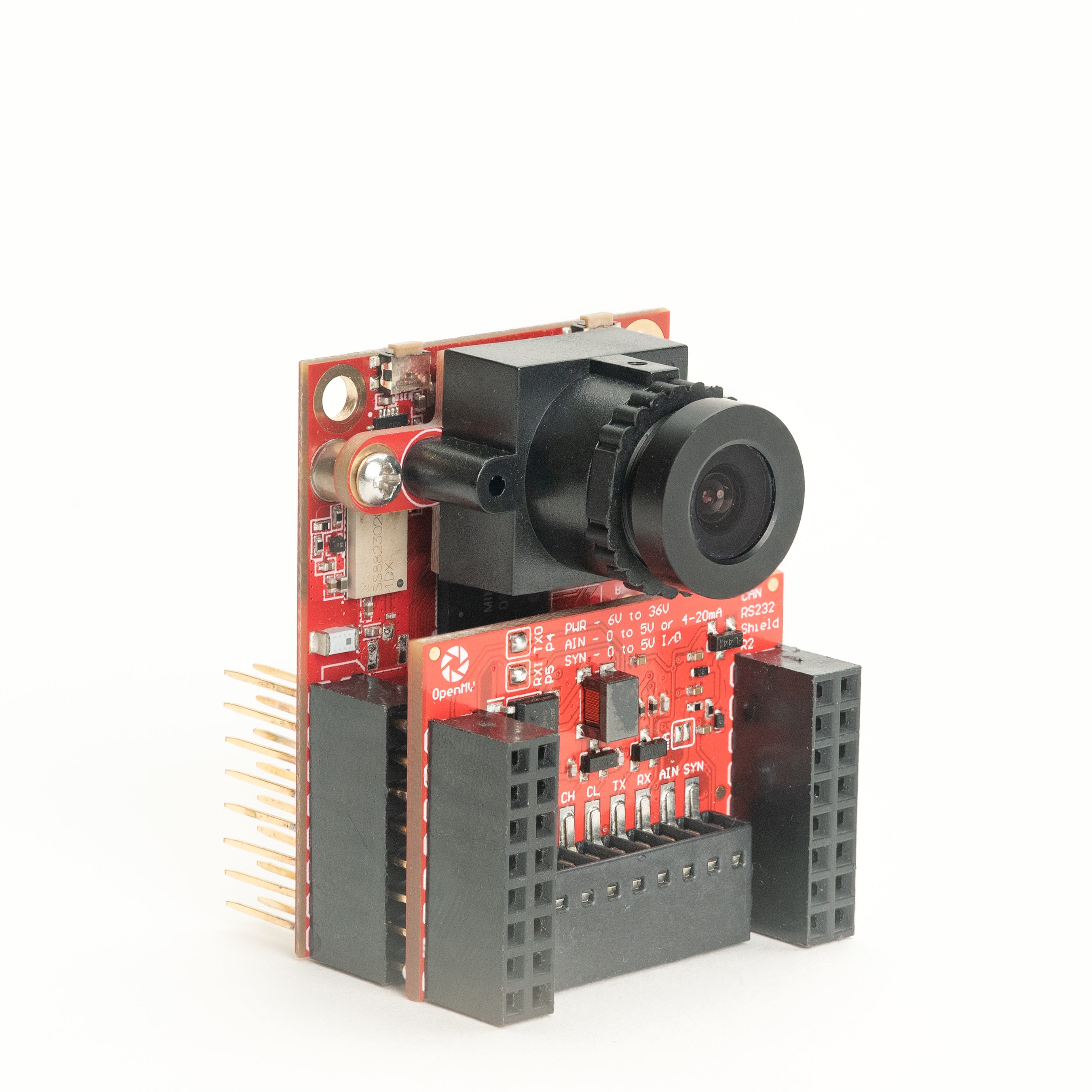
For full datasheet, photos, and ordering see the CAN/RS232 Shield product page.
Highlights
8 Mb/s CAN-FD with on-board termination and filtering
1 Mb/s RS-232 with integrated filtering
6-36 V input, reverse-voltage tolerant
0-5 V ADC input with ±36 V overvoltage protection
0-5 V digital I/O for camera-sync triggers, short-circuit protected
Pinout
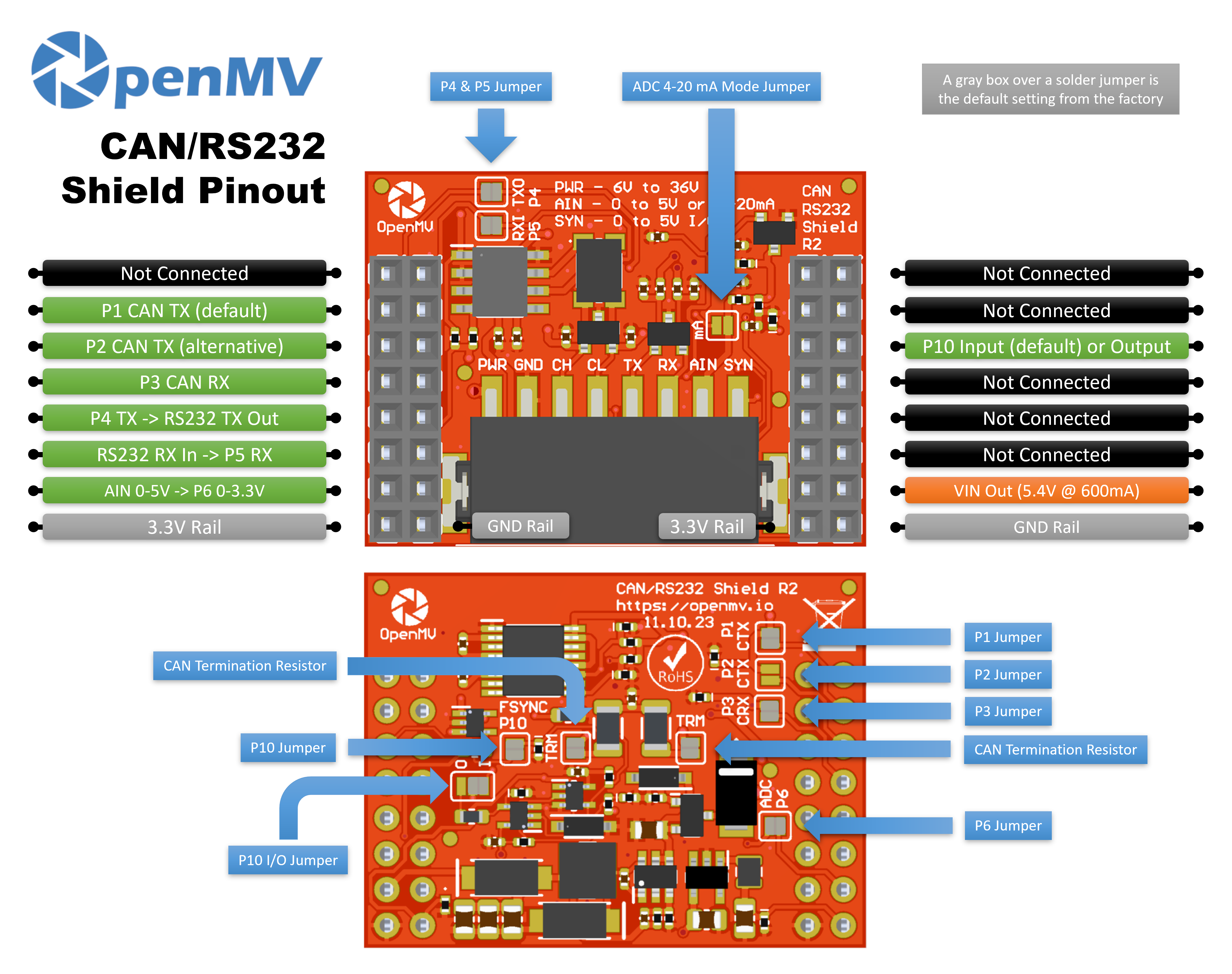
Pin reference
Pin |
Function |
|---|---|
P1 |
CAN TX → transceiver in (default) |
P2 |
CAN TX → transceiver in (alternative) |
P3 |
CAN RX ← transceiver out |
P4 |
RS-232 TX → drives the line out |
P5 |
RS-232 RX ← receives the line in |
P6 |
Level-shifted AIN readback (0–3.3 V on P6) |
P10 |
SYN — open-drain digital I/O on the terminal block |
PWR in |
6–36 V wide input on the terminal block (reverse-voltage tolerant) |
AIN in |
Analog input on the terminal block |
VIN out |
5.4 V at up to 600 mA from the on-board regulator |
3.3V rail |
Powers the shield’s on-board electronics |
GND rail |
Common ground |
Note
AIN is overvoltage-protected up to ±36 V and defaults to a 0–5 V voltage input, scaled down to 0–3.3 V on P6. Bridge the 4–20 mA mode shunt on the front of the shield to switch AIN to a 4–20 mA current-loop input.
Note
SYN is an open-drain digital line, pulled up to 3.3 V on the camera side and 5 V on the SYN terminal side. By default it’s an input — the shield level-shifts 0–5 V on SYN down to 0–3.3 V on P10. Change the on-board solder jumper to flip P10 into an output, level-shifting 0–3.3 V on P10 up to 0–5 V on SYN.
Note
Each of P1, P2, P3, P4, P5, P6, and P10 can be reclaimed for unrelated use. P1, P3, P4, P5, P6, and P10 are connected by default — P1, P3, P6, and P10 through back-side solder jumpers, P4 and P5 through front-side solder jumpers. Open the jumper on any pin you want to free. P2 defaults to disconnected: bridge its back-side jumper to route CAN TX to P2 instead (and open P1’s back-side jumper to release P1).
Note
The P1/P2 split exists so the shield works across processor families. The OpenMV Cam IMXRT boards (RT1062) can route CAN to P1, so they use the default mapping. STM32 boards can’t reach P1 with their CAN peripheral, so bridge P2’s back-side jumper (and open P1’s) to use the alternative.
Note
The CAN bus termination is connected by default — split into two 60 Ω halves in series between CANH and CANL with a cap to ground at the midpoint (a 120 Ω AC-coupled split termination). Open the two solder pads to disconnect each half independently.
Usage
Note
The CAN(0) and UART(1) peripheral numbers below follow
the IMXRT mapping (default P1 wiring). On another processor the
bus wired to these pins may be different — check your board’s
reference.
Send and receive CAN-FD frames — TX on P1 (default) or P2 (alternative), RX on P3:
from machine import CAN

can = CAN(2, 1_000_000)
can.set_filters(None)
can.send(0x123, b"\xDE\xAD\xBE\xEF")
print(can.recv())
Echo bytes over RS-232 on P4 (TX) / P5 (RX):
from machine import UART

uart = UART(1, baudrate=115200)
uart.write("hello\n")
print(uart.read())
Read the AIN terminal-block input through the level-shifted P6 pin:
from machine import ADC
import time

ain = ADC("P6")

while True:
    v = ain.read_u16() * 3.3 / 65535
    print("AIN:", v * (5.0 / 3.3), "V")
    time.sleep_ms(100)
React to a falling edge on the SYN line — for example, to sync the camera with another device pulling SYN low:
from machine import Pin

def on_sync(pin):
    print("SYN falling edge")

syn = Pin("P10", Pin.IN)
syn.irq(on_sync, Pin.IRQ_FALLING)