RS422/RS485 Shield
The RS422/RS485 Shield gives the OpenMV Cam a long-distance differential serial link suited to industrial buses, with wide-input power, surge protection, and ADC/digital I/O.

For full datasheet, photos, and ordering see the RS422/RS485 Shield product page.
Highlights
10 Mb/s RS-422 or RS-485 with on-board termination
6-36 V input, reverse-voltage tolerant
0-5 V ADC input with ±36 V overvoltage protection
0-5 V digital I/O for camera-sync triggers, short-circuit protected
Pinout
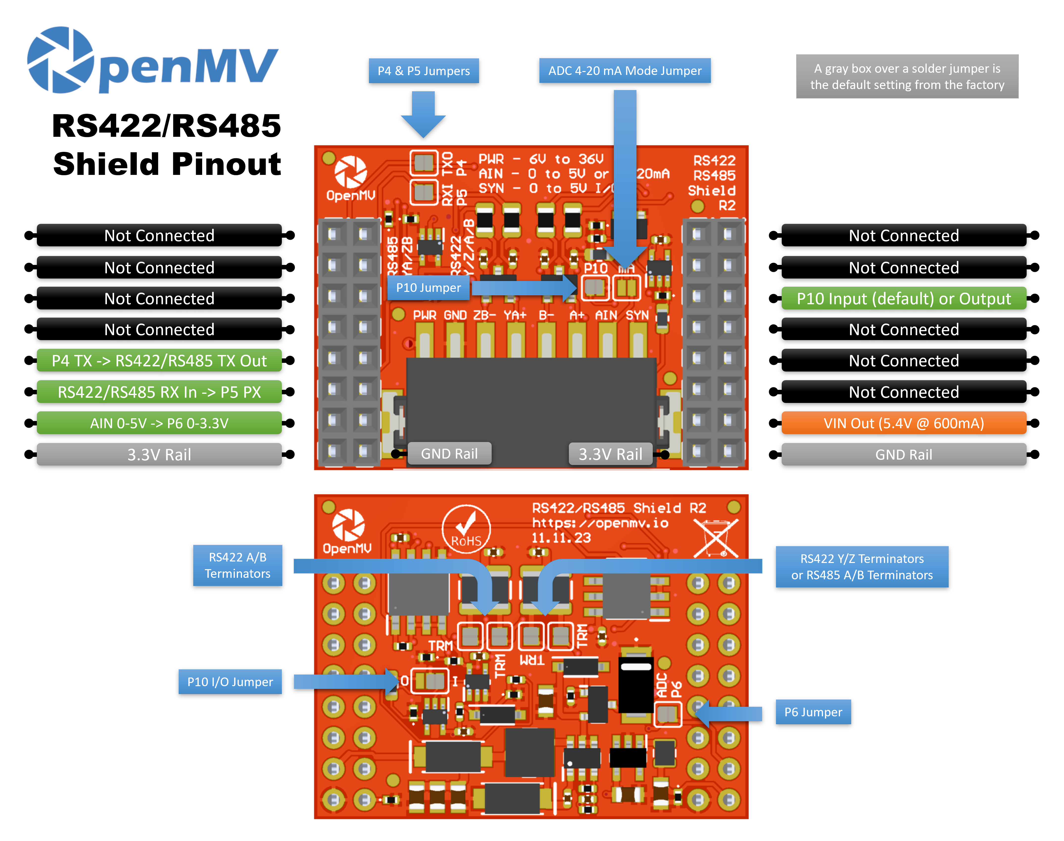
Pin reference
Pin |
Function |
|---|---|
P4 |
RS-422 / RS-485 TX → drives the differential line out |
P5 |
RS-422 / RS-485 RX ← receives differential line in |
P6 |
Level-shifted AIN readback (0–3.3 V on P6) |
P10 |
SYN — open-drain digital I/O on the terminal block |
PWR in |
6–36 V wide input on the terminal block (reverse-voltage tolerant) |
AIN in |
Analog input on the terminal block |
VIN out |
5.4 V at up to 600 mA from the on-board regulator |
3.3V rail |
Powers the shield’s on-board electronics |
GND rail |
Common ground |
Note
AIN is overvoltage-protected up to ±36 V and defaults to a 0–5 V voltage input, scaled down to 0–3.3 V on P6. Bridge the 4–20 mA mode shunt on the front of the shield to switch AIN to a 4–20 mA current-loop input.
Note
SYN is an open-drain digital line, pulled up to 3.3 V on the camera side and 5 V on the SYN terminal side. By default it’s an input — the shield level-shifts 0–5 V on SYN down to 0–3.3 V on P10. Change the on-board solder jumper to flip P10 into an output, level-shifting 0–3.3 V on P10 up to 0–5 V on SYN.
Note
Each of P4, P5, P6, and P10 is connected to the camera by default through a solder jumper — open the jumper on any pin you want to reclaim for unrelated use. P6’s jumper is on the back of the shield; P4, P5, and P10 are on the front.
Note
The on-board termination resistors are connected by default — open the corresponding back-side solder jumpers to disconnect them. Two cover the RS-422 A/B pair and two cover the RS-422 Y/Z pair (which doubles as the RS-485 A/B termination), four jumpers in total.
About RS-422 and RS-485
Both standards send serial data as a balanced (differential) signal over twisted pairs for long-distance, noise-tolerant links:
RS-422 is full-duplex over four wires. A driver transmits on a dedicated TX pair labeled Y/Z, and the peer transmits back on a separate RX pair labeled A/B. One transmitter and up to ten receivers per pair.
RS-485 is typically half-duplex over two wires. Transmit and receive share a single pair, called A/B in RS-485 terminology but physically the same Y/Z lines on this shield. Up to thirty-two nodes can share the bus and any of them can drive it.
How the shield supports both
The shield carries two THVD1426 transceivers, each able to handle either standard:
The first transceiver drives the Y/Z pair (which doubles as the RS-485 A/B pair). It is the only one with its driver hooked up, so all outbound traffic from the camera goes out this pair regardless of mode.
The second transceiver drives the A/B pair. Its driver is tied off — this transceiver is receive-only and only matters in 4-wire RS-422 mode.
Both transceivers’ receivers are always enabled, and their RX outputs are AND’d together onto a single receive line back to the camera:
In 2-wire RS-485 mode, only the first transceiver is active. Wire the bus to Y/Z; the A/B side sits idle and the AND gate just passes the first transceiver’s RX through.
In 4-wire RS-422 mode, the peer transmits to the camera on the A/B pair (picked up by the second transceiver) while the camera transmits on Y/Z (with the first transceiver’s own receiver echoing its outgoing data back). The AND gate combines them — whichever pair sees a low pulse (start bit, data) reaches the camera.
The terminal-block labels reflect the dual mapping:
RS-422 (4-wire) — TX out on Y/Z, RX in on A/B.
RS-485 (2-wire) — TX/RX share the Y/Z pair (= A/B in RS-485 nomenclature). Leave the A/B terminals on the shield unconnected.
Usage
Note
The UART(3) peripheral number below follows the STM32 mapping.
On another processor the bus wired to these pins may be different
— check your board’s reference.
Talk to a differential serial peer on P4 (TX) / P5 (RX):
from machine import UART

uart = UART(3, baudrate=115200)
uart.write("hello\n")
print(uart.read())
Read the AIN terminal-block input through the level-shifted P6 pin:
from machine import ADC
import time

ain = ADC("P6")

while True:
    v = ain.read_u16() * 3.3 / 65535
    print("AIN:", v * (5.0 / 3.3), "V")
    time.sleep_ms(100)
React to a falling edge on the SYN line — for example, to sync the camera with another device pulling SYN low:
from machine import Pin

def on_sync(pin):
    print("SYN falling edge")

syn = Pin("P10", Pin.IN)
syn.irq(on_sync, Pin.IRQ_FALLING)