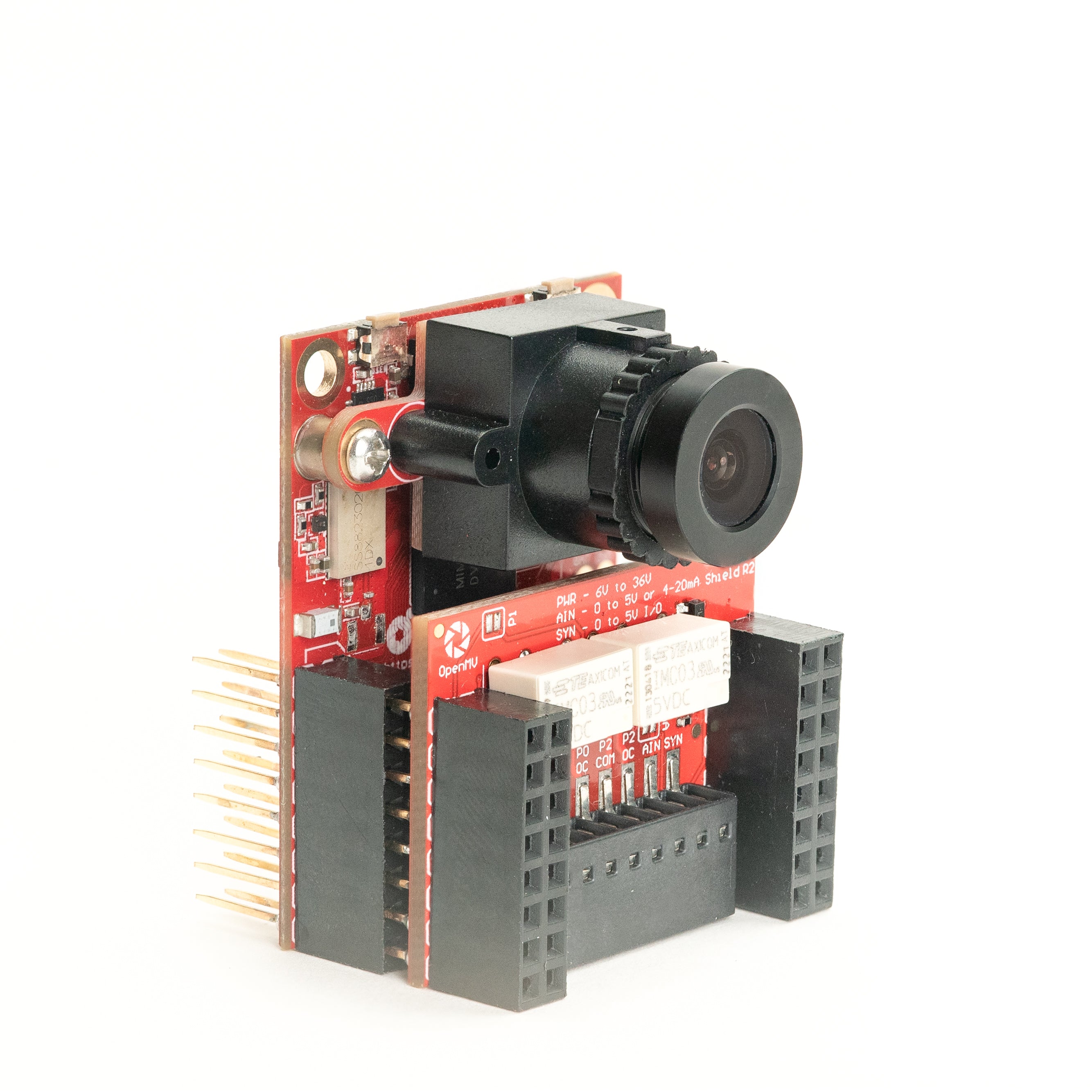
Relay Shield
The Relay Shield switches two high-power AC or DC loads up to 60 W per relay from the OpenMV Cam, with a 6-36 V input plus an ADC input and a digital I/O line for sync.
For full datasheet, photos, and ordering see the Relay Shield product page.
Highlights
Dual relays — 60 W each (15-220 V DC, 125-260 V AC)
6-36 V input with reverse-voltage tolerance
0-5 V ADC input with ±36 V overvoltage protection
0-5 V digital I/O for camera-sync triggers
Pinout
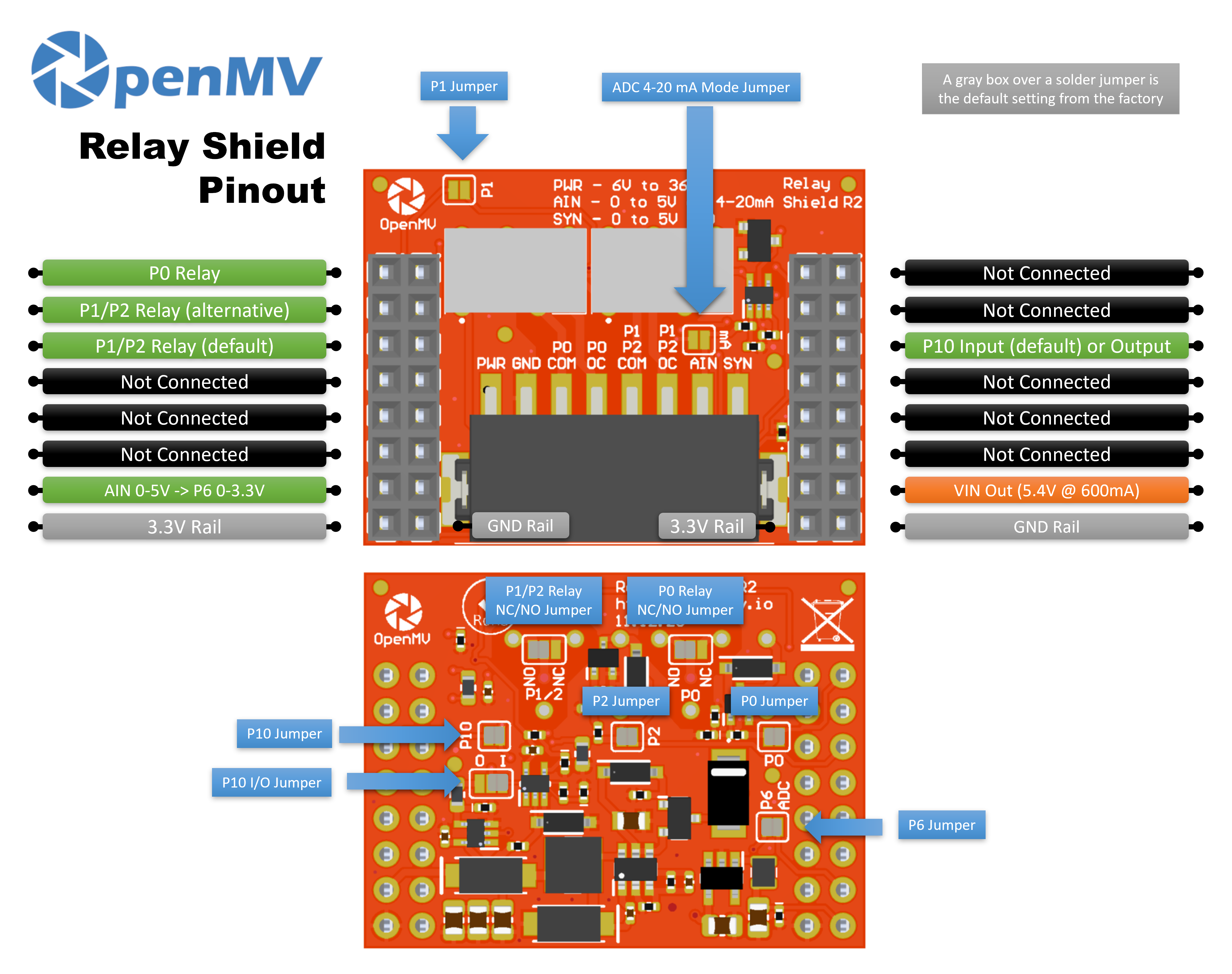
Pin reference
Pin |
Function |
|---|---|
P0 |
Relay 1 control |
P1 |
Relay 2 control (alternative) |
P2 |
Relay 2 control (default) |
P6 |
Level-shifted AIN readback (0–3.3 V on P6) |
P10 |
SYN — open-drain digital I/O on the terminal block |
PWR in |
6–36 V wide input on the terminal block (reverse-voltage tolerant) |
AIN in |
Analog input on the terminal block |
VIN out |
5.4 V at up to 600 mA from the on-board regulator |
3.3V rail |
Powers the shield’s on-board electronics |
GND rail |
Common ground |
Note
AIN is overvoltage-protected up to ±36 V and defaults to a 0–5 V voltage input, scaled down to 0–3.3 V on P6. Bridge the 4–20 mA mode shunt on the front of the shield to switch AIN to a 4–20 mA current-loop input.
Note
SYN is an open-drain digital line, pulled up to 3.3 V on the camera side and 5 V on the SYN terminal side. By default it’s an input — the shield level-shifts 0–5 V on SYN down to 0–3.3 V on P10. Change the on-board solder jumper to flip P10 into an output, level-shifting 0–3.3 V on P10 up to 0–5 V on SYN.
Note
Each of P0, P1, P2, P6, and P10 can be reclaimed for unrelated use. P0, P2, P6, and P10 are connected by default through back-side solder jumpers — open the jumper on any pin you want to free. P1 defaults to disconnected: bridge its front-side jumper to route Relay 2 to P1 instead (and open P2’s back-side jumper to release P2).
Note
The relays default to normally-open (NO). Solder bridges on the bottom of the shield switch them to normally-closed (NC).
Usage
Toggle the two relays from P0 and P1:
from machine import Pin
import time

relay1 = Pin("P0", Pin.OUT)
relay2 = Pin("P1", Pin.OUT)

while True:
    relay1.on()
    relay2.off()
    time.sleep(1)
    relay1.off()
    relay2.on()
    time.sleep(1)
Read the AIN terminal-block input through the level-shifted P6 pin:
from machine import ADC
import time

ain = ADC("P6")

while True:
    v = ain.read_u16() * 3.3 / 65535
    print("AIN:", v * (5.0 / 3.3), "V")
    time.sleep_ms(100)
React to a falling edge on the SYN line — for example, to sync the camera with another device pulling SYN low:
from machine import Pin

def on_sync(pin):
    print("SYN falling edge")

syn = Pin("P10", Pin.IN)
syn.irq(on_sync, Pin.IRQ_FALLING)