
 OpenMV MicroPython
AE3 OLED Breakout
The AE3 OLED Breakout pairs the OpenMV AE3 with a 128 × 128 RGB OLED, a 5‑way joystick, and a 10‑pin ARM SWD header for stand‑alone preview, simple input, and JTAG/SWD debug.
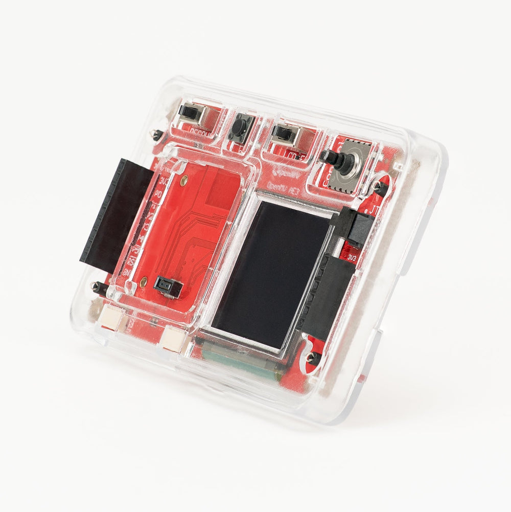
For full datasheet, photos, and ordering see the AE3 OLED Breakout product page.
Highlights
128 × 128 RGB OLED driven by an SSD1351 controller over SPI.
AS90R 5‑way joystick with a centre push button, exposed on the
P4/P5I²C bus.Reset button and recovery switch for secure‑enclave UART access.
OLED disconnect switch to electrically remove the panel from the SPI bus.
Two Qwiic connectors on the same
P4/P5I²C bus.ARM 10‑pin Cortex Debug header for SWD/JTAG debugging.
Four ground hook test points.
Note
Four corner M1.6 mounting holes let you bolt the breakout down to an enclosure or fixture.
Pin reference
All AE3 signals on the breakout are taken from the B2B header on
the bottom of the AE3 and brought out to two side pin headers —
P0–P5 on one side, P6–P9 on the other — both
3.3 V referenced. The full alt function list for each pin
lives on the OpenMV AE3
page; the breakout uses the pins as follows:
Pin |
Reference |
AE3 features |
Breakout use |
|---|---|---|---|
P0 |
3.3 V |
SPI0 MOSI / I2C2 SCL / UART4 TX / TIM0 T1 / PDM D3 |
OLED SPI MOSI |
P1 |
3.3 V |
SPI0 MISO / I2C2 SDA / UART4 RX / TIM0 T0 |
free |
P2 |
3.3 V |
SPI0 SCLK / LPI2C SDA / UART5 TX / TIM1 T1 |
OLED SPI SCLK |
P3 |
3.3 V |
SPI0 SS / LPI2C SCL / UART5 RX / TIM1 T0 / PDM C3 |
OLED SPI CS |
P4 |
3.3 V |
I2C1 SCL / UART1 TX / TIM2 T1 / PDM C0 / CAN TX |
Joystick / Qwiic I²C SCL |
P5 |
3.3 V |
I2C1 SDA / UART1 RX / TIM2 T0 / PDM D0 / CAN RX |
Joystick / Qwiic I²C SDA |
RESET |
3.3 V |
NRST |
Press the on‑board RESET button or pull to GND to reset the AE3 |
P6 |
3.3 V |
I2C1 SDA / UART3 CTS / TIM9 T0 |
free |
P7 |
3.3 V |
I2C1 SCL / UART3 RTS / TIM9 T1 |
OLED RESET |
P8 |
3.3 V |
I3C SDA / UART3 RX / TIM5 T0 / ADC ch S10 |
OLED DC (register select) |
P9 |
3.3 V |
I3C SCL / UART3 TX / TIM5 T1 / ADC ch S11 |
Joystick IRQ (active low on state change) |
3.3V rail |
— |
— |
Powers the OLED, joystick expander, and Qwiic devices |
GND rail |
— |
— |
Common ground |
Note
The recovery switch flips an internal USB mux on the AE3: the AE3’s own USB pins are disconnected from the USB‑C port, and a USB‑to‑serial converter on the secure‑enclave UART is connected to the port in their place. With the switch engaged, host‑side Alif tools can talk to the secure enclave to reprogram the AE3’s bootloader. Leave the switch disabled for normal operation so the USB‑C port acts as the AE3’s USB.
Note
The OLED enable switch has to be on for the OLED to work —
it gates power to the panel and connects the OLED control pins
(P0, P2, P3, P7, P8) through to the AE3’s
GPIO. With the switch off only P4, P5, and P9 stay
wired through. The current switch state shows up on the
joystick expander as bit 0x40 — the raw expander pin reads
low when the switch is enabled.
Qwiic headers
Two Qwiic 4‑pin JST‑SH 1.0 mm connectors sit on the breakout
and share the same P4/P5 I²C bus as the on‑board joystick
expander, so additional Qwiic devices must avoid the joystick
expander’s address (0x63).
Pin |
Signal |
|---|---|
1 |
GND |
2 |
+3.3 V |
3 |
SDA ( |
4 |
SCL ( |
JTAG header
The 10‑pin 1.27 mm ARM Cortex Debug header on the breakout is
wired straight to the AE3’s SWD/JTAG lines. All signals are
1.8 V referenced — use a level‑shifting probe or one whose
target voltage tracks VCC_REF (pin 1).
Pin |
Signal |
|---|---|
1 |
VCC_REF (+1.8 V) |
2 |
TMS (SWDIO) |
3 |
+1.8 V |
4 |
TCK (SWCLK) |
5 |
GND |
6 |
TDO (SWO) |
7 |
key (no pin) |
8 |
TDI |
9 |
GND |
10 |
DEBUG_RST_N (JTAG/debug reset — separate from the system NRST) |
Usage
Drive the OLED through display.SPIDisplay with an
SSD1351 controller instance. Stream
camera frames to the 128 × 128 panel:
import csi
import time
import display
import image

csi0 = csi.CSI()
csi0.reset()
csi0.pixformat(csi.RGB565)
csi0.framesize(csi.VGA)
csi0.window((400, 400))

lcd = display.SPIDisplay(width=128, height=128,
                         controller=display.SSD1351())
clock = time.clock()

while True:
    clock.tick()
    lcd.write(csi0.snapshot(),
              hint=image.CENTER | image.SCALE_ASPECT_KEEP)
    print(clock.fps())
Read the 5‑way joystick through the frozen
pca9674a.PCA9674A driver. The expander asserts P9 on
state changes, so wire an IRQ callback that latches the new
button state. The buttons are active‑low on the expander; the
code below XORs the read with 0xFF so a set bit in state
means pressed:
Bit |
Direction |
|---|---|
|
Joystick right |
|
Joystick up |
|
Joystick left |
|
Joystick down |
|
Joystick centre push |
|
OLED enable switch (set in |
import csi
import time
import display
from pca9674a import PCA9674A
from machine import I2C

csi0 = csi.CSI()
csi0.reset()
csi0.pixformat(csi.RGB565)
csi0.framesize(csi.VGA)
csi0.window((400, 400))

lcd = display.SPIDisplay(width=128, height=128,
                         controller=display.SSD1351())
clock = time.clock()

state = 0
cursor_x = 0
cursor_y = 0

def read_expander(pin):
    global exp, state
    # Buttons are active‑low on the expander; XOR for active‑high bits.
    state = exp.read() ^ 0xFF

exp = PCA9674A(I2C(1), irq_pin="P9", callback=read_expander)

def update_cursor():
    global cursor_x, cursor_y
    if state & 0x01:  cursor_x += 2     # Right
    if state & 0x02:  cursor_y -= 2     # Up
    if state & 0x04:  cursor_x -= 2     # Left
    if state & 0x08:  cursor_y += 2     # Down
    if state & 0x10:                    # Centre
        cursor_x = 0
        cursor_y = 0

while True:
    clock.tick()
    update_cursor()
    lcd.write(csi0.snapshot(), x=cursor_x, y=cursor_y,
              x_scale=128 / 400, y_scale=128 / 400)
    print(clock.fps())