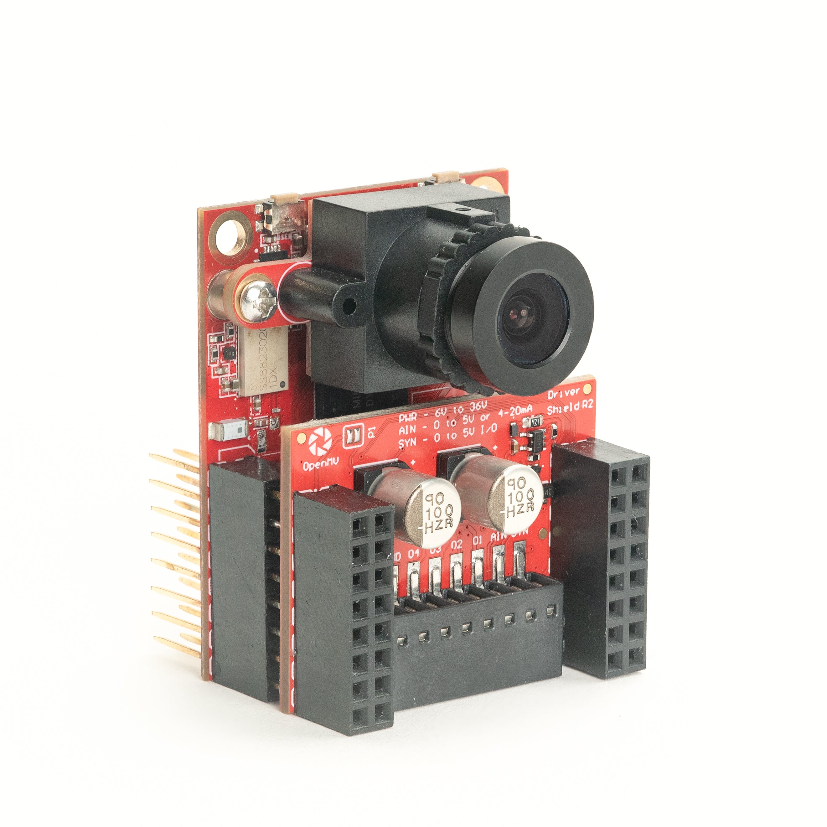
Driver Shield
The Driver Shield runs two 3 A motors or four independent 1.5 A line drivers from a wide 6-36 V supply, giving the OpenMV Cam a rugged motor-control front-end with reverse-voltage and surge protection.
For full datasheet, photos, and ordering see the Driver Shield product page.
Highlights
Dual 3 A motor drivers OR quad 1.5 A line drivers, 6-36 V
Reverse-voltage and transient-surge protection on the input
0-5 V ADC input with ±36 V overvoltage protection
0-5 V digital I/O for camera-sync triggers, short-circuit protected
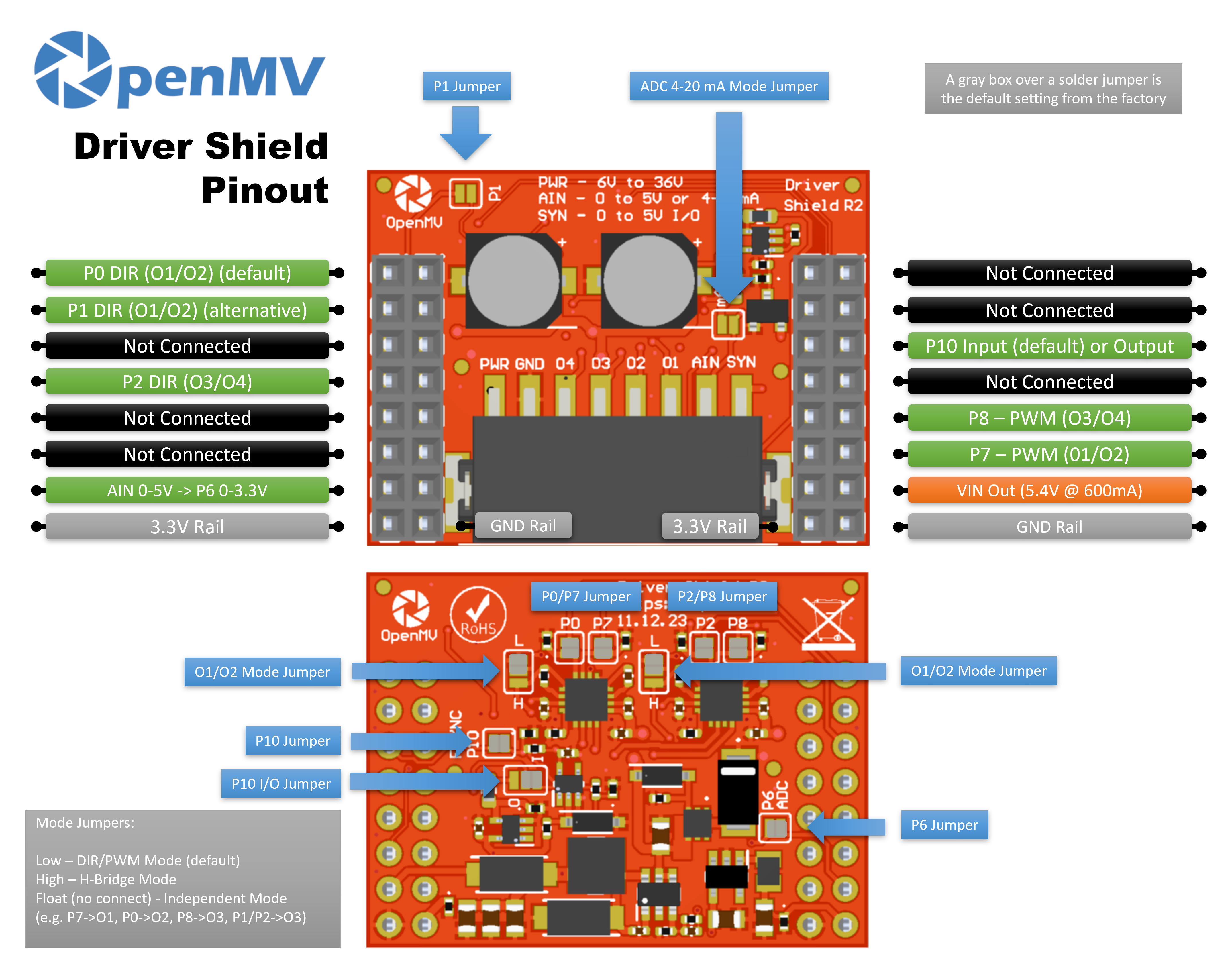
Pinout
Pin reference
Pin |
Function |
|---|---|
P0 |
DIR for output pair O1/O2 |
P1 |
DIR for output pair O3/O4 (alternative) |
P2 |
DIR for output pair O3/O4 (default) |
P6 |
Level-shifted AIN readback (0–3.3 V on P6) |
P7 |
PWM for output pair O1/O2 |
P8 |
PWM for output pair O3/O4 |
P10 |
SYN — open-drain digital I/O on the terminal block |
PWR in |
6–36 V wide input on the terminal block (reverse-voltage tolerant) |
AIN in |
Analog input on the terminal block |
VIN out |
5.4 V at up to 600 mA from the on-board regulator |
3.3V rail |
Powers the shield’s on-board electronics |
GND rail |
Common ground |
Note
AIN is overvoltage-protected up to ±36 V and defaults to a 0–5 V voltage input, scaled down to 0–3.3 V on P6. Bridge the 4–20 mA mode shunt on the front of the shield to switch AIN to a 4–20 mA current-loop input.
Note
SYN is an open-drain digital line, pulled up to 3.3 V on the camera side and 5 V on the SYN terminal side. By default it’s an input — the shield level-shifts 0–5 V on SYN down to 0–3.3 V on P10. Change the on-board solder jumper to flip P10 into an output, level-shifting 0–3.3 V on P10 up to 0–5 V on SYN.
Note
Each of P0, P1, P2, P6, P7, P8, and P10 can be reclaimed for unrelated use. P0, P2, P6, P7, P8, and P10 are connected by default through back-side solder jumpers — open the jumper on any pin you want to free. P1 defaults to disconnected: bridge its front-side jumper to route DIR for O3/O4 to P1 instead (and open P2’s back-side jumper to release P2).
Note
Two mode jumpers on the back of the shield — one per H-bridge — independently set each output pair into one of three modes. Each jumper has L and H markings to show which side selects which state:
Low (default) — DIR/PWM mode: one DIR pin + one PWM pin per bridge.
High — H-bridge mode: both pins drive the bridge directly via the chip’s two-input truth table.
Float (no connect) — independent mode: each pin becomes a stand-alone line driver routed to one output.
Each DRV8876 is current-limited to 3 A total per chip — that’s 3 A through one bridge (DIR/PWM or H-bridge mode) or 1.5 A per output split across the two outputs (independent mode).
Usage
DIR/PWM mode (default)
Drive a brushed DC motor on output pair O1/O2 — set direction on P0 and apply a PWM speed signal on P7. The loop below ramps the duty cycle up to full speed and back down, then flips direction and repeats:
from machine import Pin, PWM
import time

direction = Pin("P0", Pin.OUT)
speed = PWM(Pin("P7"), freq=20_000, duty_u16=0)


def ramp(target):
    for duty in range(0, target, 1024):
        speed.duty_u16(duty)
        time.sleep_ms(10)
    for duty in range(target, -1, -1024):
        speed.duty_u16(duty)
        time.sleep_ms(10)


while True:
    direction.value(1)  # forward
    ramp(65_535)
    direction.value(0)  # reverse
    ramp(65_535)
The two H-bridges can also drive a bipolar stepper — hold both PWM channels at full drive and step the DIR pins through the four-phase sequence:
from machine import Pin, PWM
import time

dir12 = Pin("P0", Pin.OUT)
dir34 = Pin("P2", Pin.OUT)
PWM(Pin("P7"), freq=20_000, duty_u16=65_535)  # full drive on O1/O2
PWM(Pin("P8"), freq=20_000, duty_u16=65_535)  # full drive on O3/O4

SEQUENCE = [(1, 1), (0, 1), (0, 0), (1, 0)]


def step(forward=True):
    for a, b in SEQUENCE if forward else reversed(SEQUENCE):
        dir12.value(a)
        dir34.value(b)
        time.sleep_ms(5)


while True:
    for _ in range(50):  # ~1 revolution forward (200 phases)
        step()
    for _ in range(50):  # ~1 revolution backward
        step(forward=False)
H-bridge mode
With the mode jumper set high, both bridge pins drive the H-bridge directly. For O1/O2 the truth table is:
(P0, P7) = (L, L)→ coast (outputs Hi-Z)(P0, P7) = (L, H)→ forward (O1 = H, O2 = L)(P0, P7) = (H, L)→ reverse (O1 = L, O2 = H)(P0, P7) = (H, H)→ brake (outputs both low)
(O3/O4 follows the same table with P1/P2 and P8.) The loop below cycles a motor through forward → brake → reverse → coast on output pair O1/O2:
from machine import Pin
import time

p0 = Pin("P0", Pin.OUT)
p7 = Pin("P7", Pin.OUT)


def drive(a, b):
    p0.value(a)
    p7.value(b)


while True:
    drive(0, 1)         # forward
    time.sleep(1)
    drive(1, 1)         # brake
    time.sleep_ms(500)
    drive(1, 0)         # reverse
    time.sleep(1)
    drive(0, 0)         # coast
    time.sleep_ms(500)
Either pin can be swapped for a machine.PWM channel for
proportional drive — e.g. (P0=0, P7=PWM) gives forward/coast at
the PWM duty, (P0=1, P7=PWM) gives reverse/brake at (100 % −
duty). The loop below ramps the duty up and back down with P0 held
at 0 (forward/coast):
from machine import Pin, PWM
import time

p0 = Pin("P0", Pin.OUT, value=0)
p7 = PWM(Pin("P7"), freq=20_000, duty_u16=0)

while True:
    for duty in range(0, 65_536, 1024):
        p7.duty_u16(duty)
        time.sleep_ms(10)
    for duty in range(65_535, -1, -1024):
        p7.duty_u16(duty)
        time.sleep_ms(10)
Independent mode
With the mode jumper floating, each pin becomes a stand-alone line driver routed to one output — useful for solenoids, relays, or any on/off load that doesn’t need an H-bridge. The mapping is P7 → O1, P0 → O2, P8 → O3, and P1 (or P2) → O4:
from machine import Pin
import time

outputs = [
    Pin("P7", Pin.OUT),  # O1
    Pin("P0", Pin.OUT),  # O2
    Pin("P8", Pin.OUT),  # O3
    Pin("P2", Pin.OUT),  # O4
]

while True:
    for o in outputs:    # walk a single high pulse across O1–O4
        o.value(1)
        time.sleep_ms(200)
        o.value(0)
Any of the four pins can also be PWM’d via machine.PWM for
proportional drive — for example, fade each output up and down in
turn:
from machine import Pin, PWM
import time

outputs = [
    PWM(Pin("P7"), freq=1_000, duty_u16=0),  # O1
    PWM(Pin("P0"), freq=1_000, duty_u16=0),  # O2
    PWM(Pin("P8"), freq=1_000, duty_u16=0),  # O3
    PWM(Pin("P2"), freq=1_000, duty_u16=0),  # O4
]

while True:
    for o in outputs:
        for duty in range(0, 65_536, 1024):
            o.duty_u16(duty)
            time.sleep_ms(5)
        for duty in range(65_535, -1, -1024):
            o.duty_u16(duty)
            time.sleep_ms(5)
Other I/O
Read the AIN terminal-block input through the level-shifted P6 pin:
from machine import ADC
import time

ain = ADC("P6")

while True:
    v = ain.read_u16() * 3.3 / 65535
    print("AIN:", v * (5.0 / 3.3), "V")
    time.sleep_ms(100)
React to a falling edge on the SYN line — for example, to sync the camera with another device pulling SYN low:
from machine import Pin

def on_sync(pin):
    print("SYN falling edge")

syn = Pin("P10", Pin.IN)
syn.irq(on_sync, Pin.IRQ_FALLING)