
 OpenMV MicroPython
AE3 Battery Shield
The AE3 Battery Shield powers the OpenMV AE3
from a wide range of supplies — 5–36 V, a 3.7 V Li‑Po cell, or
1.8–5.5 V for 3 alkaline cells in series — and adds an SPI microSD
card socket on P0–P3. All three power inputs land on JST terminals; the
shield ships with a JST‑to‑pigtail adapter for the wide input and
a JST‑to‑DC‑barrel‑jack adapter for the alkaline input.
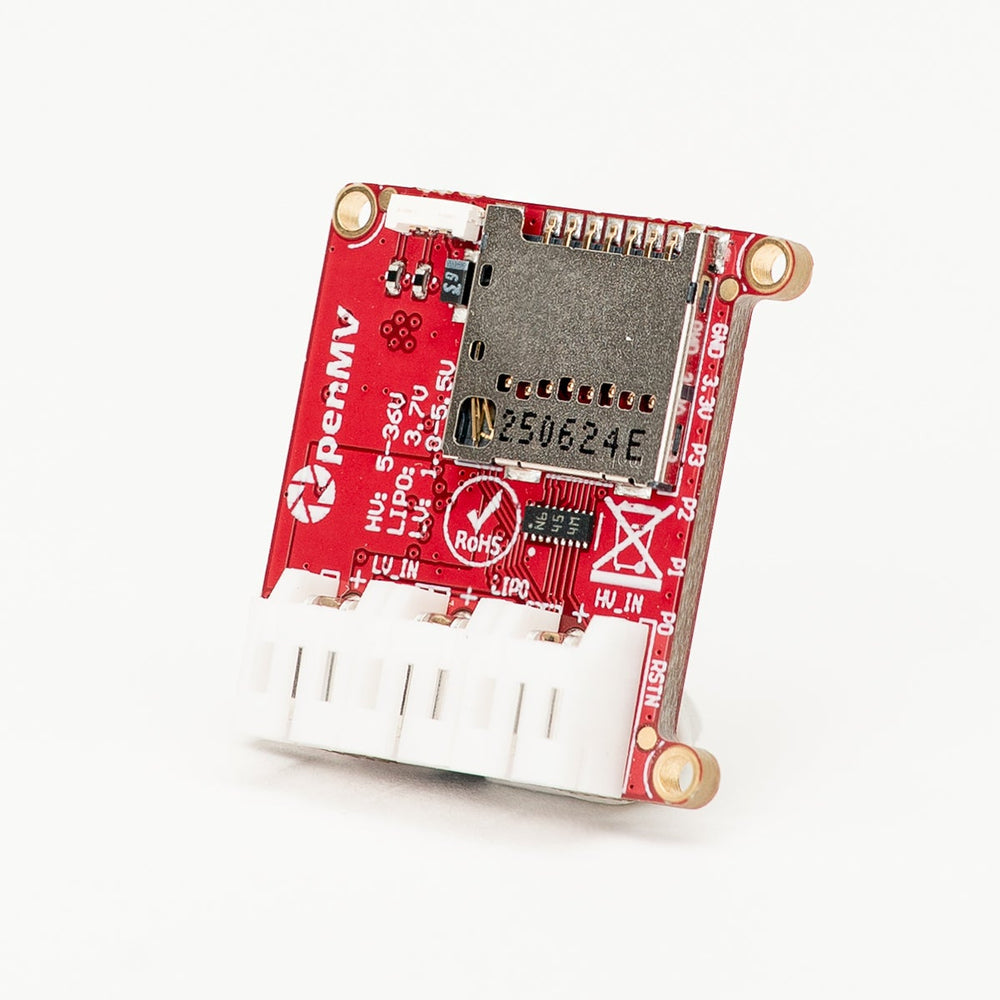
For full datasheet, photos, and ordering see the AE3 Battery Shield product page.
Highlights
HV PWR — 5–36 V, reverse‑voltage tolerant to −36 V. Powers the AE3 at 3.3 V (up to 600 mA).
BAT — 3.7 V single‑cell Li‑Po. Powers the AE3 at 3.0 V (up to 800 mA). The on‑board charger runs at a 100 mA charge current whenever 3.3 V is available on the shield — supplied by USB, HV PWR, or 3.3 V fed to the AE3 through its Qwiic connector. A 6.25 hr safety timer caps the supported battery capacity at 625 mAh.
LV PWR — 1.8–5.5 V for 3 alkaline cells in series, reverse‑voltage tolerant to −5.5 V. Powers the AE3 at 3.0 V (up to 800 mA).
microSD card socket wired to
P0–P3over SPI, with a software‑controlled power switch onP11.
Note
The shield ships with a case that holds the AE3 firmly against the connector. Four corner M1.6 mounting holes let you bolt the shield down to an enclosure or fixture.
Tip
Use the battery life estimator to model how long the AE3 powered through this shield will run on a given battery for a given active / deep-sleep duty cycle.
Pin reference
Pin |
Function |
|---|---|
P0 |
microSD SPI MOSI |
P1 |
microSD SPI MISO |
P2 |
microSD SPI SCLK |
P3 |
microSD SPI CS |
P6 |
Charger power‑good (low when 3.3 V is present on the shield — USB, HV PWR, or Qwiic 3.3 V; charging only happens while this is low) |
P7 |
Charger charging (low while the Li‑Po is being charged) |
P8 |
Li‑Po battery voltage monitor — shield divides 0–5 V down to 0–1.8 V at the pin |
P9 |
LV input voltage monitor — shield divides 0–6 V down to 0–1.8 V at the pin |
P11 |
microSD power enable (drive high to power the card) |
HV PWR in |
5–36 V on a JST terminal (reverse‑voltage tolerant; JST‑to‑pigtail adapter included) |
BAT in |
3.7 V single‑cell Li‑Po on a JST terminal |
LV PWR in |
1.8–5.5 V on a JST terminal for 3 alkaline cells in series (reverse‑voltage tolerant; JST‑to‑DC‑barrel‑jack adapter included) |
3.3V rail |
Powers the AE3 and the shield’s on‑board electronics |
GND rail |
Common ground |
Usage
Plug an AE3 onto the shield and connect any one of the three power inputs — the shield ORs the rails internally and feeds the AE3 from whichever source is present.
Note
With only BAT connected (no USB, HV PWR, or Qwiic 3.3 V
feeding the shield), the AE3 runs at 3.0 V off the Li‑Po, the
charger is idle, and both status LEDs are off.
The microSD socket is exposed on the AE3’s SPI bus through
machine.SPI and the standard sdcard driver. Drive
P11 high to power the card, then wrap the block device in a
VfsFat and mount it at /sdcard:
import os
import machine
import sdcard

machine.Pin("P11", machine.Pin.OUT, value=1)  # enable card power

spi = machine.SPI(0)
cs  = machine.Pin("P3", machine.Pin.OUT, value=1)

sd  = sdcard.SDCard(spi, cs, baudrate=20_000_000)
os.mount(os.VfsFat(sd), "/sdcard")
print(os.listdir("/sdcard"))
Watch the charger status by reading its two status pins. P6
(power‑good) goes low as soon as 3.3 V is present on the shield —
from USB, HV PWR, or 3.3 V fed back through the AE3’s Qwiic —
which is also when the charger is allowed to run. P7 (charging)
goes low while the Li‑Po is actually being charged. Both pins also
drive on‑board status LEDs — P6 lights a green LED, P7
lights a red LED:
from machine import Pin

pg  = Pin("P6", Pin.IN, Pin.PULL_UP)
chg = Pin("P7", Pin.IN, Pin.PULL_UP)

if not pg.value():
    print("Charger powered")
    if not chg.value():
        print("Battery charging")
    else:
        print("Battery full or no battery")
else:
    print("Running off battery only")
Monitor the Li‑Po battery and LV input voltages on P8 and
P9. The shield divides each supply down to the AE3’s 1.8 V
ADC range, so scale the reading back up by the input’s full‑scale
range:
from machine import ADC
import time

lipo = ADC("P8")    # 0–5 V at the input
lv   = ADC("P9")    # 0–6 V at the input

while True:
    # 0–1.8 V at the pin → 0–5 V on the battery rail
    vbat = lipo.read_u16() * 1.8 / 65535 * (5.0 / 1.8)
    # 0–1.8 V at the pin → 0–6 V on the LV rail
    vlv  = lv.read_u16()  * 1.8 / 65535 * (6.0 / 1.8)
    print("Li‑Po:", vbat, "V  LV:", vlv, "V")
    time.sleep_ms(500)