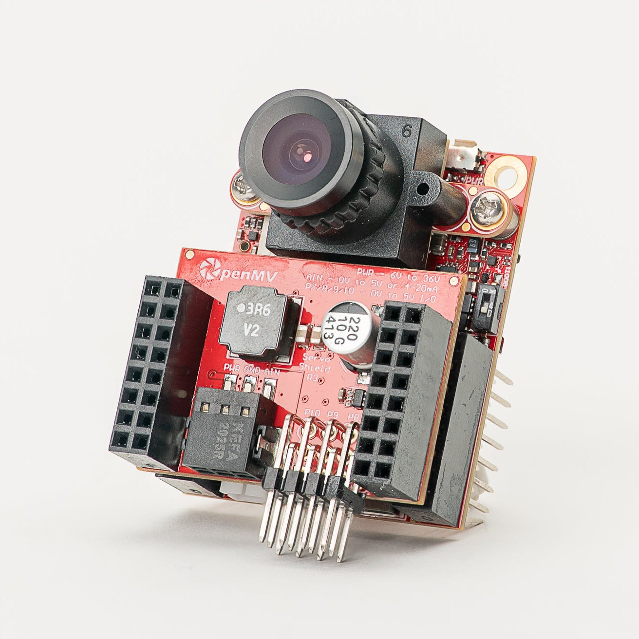
Servo Shield
The Servo Shield (v3) drives up to four standard hobby servos directly from the OpenMV Cam. Its on-board regulator accepts a 6–36 V input on the terminal block and delivers 5.6 V at up to 5 A — enough to power both the camera and the servos from a single supply.
For full datasheet, photos, and ordering see the Servo Shield product page.
Highlights
Drive up to four hobby servos via P7 / P8 / P9 / P10
6–36 V input on the terminal block (reverse-voltage tolerant)
5.6 V at up to 5 A on VIN — powers the camera and servos
0–5 V ADC input with overvoltage protection up to ±36 V
Bidirectional 0–5 V digital I/O with 3.3 V to 5 V level shifting
Pinout
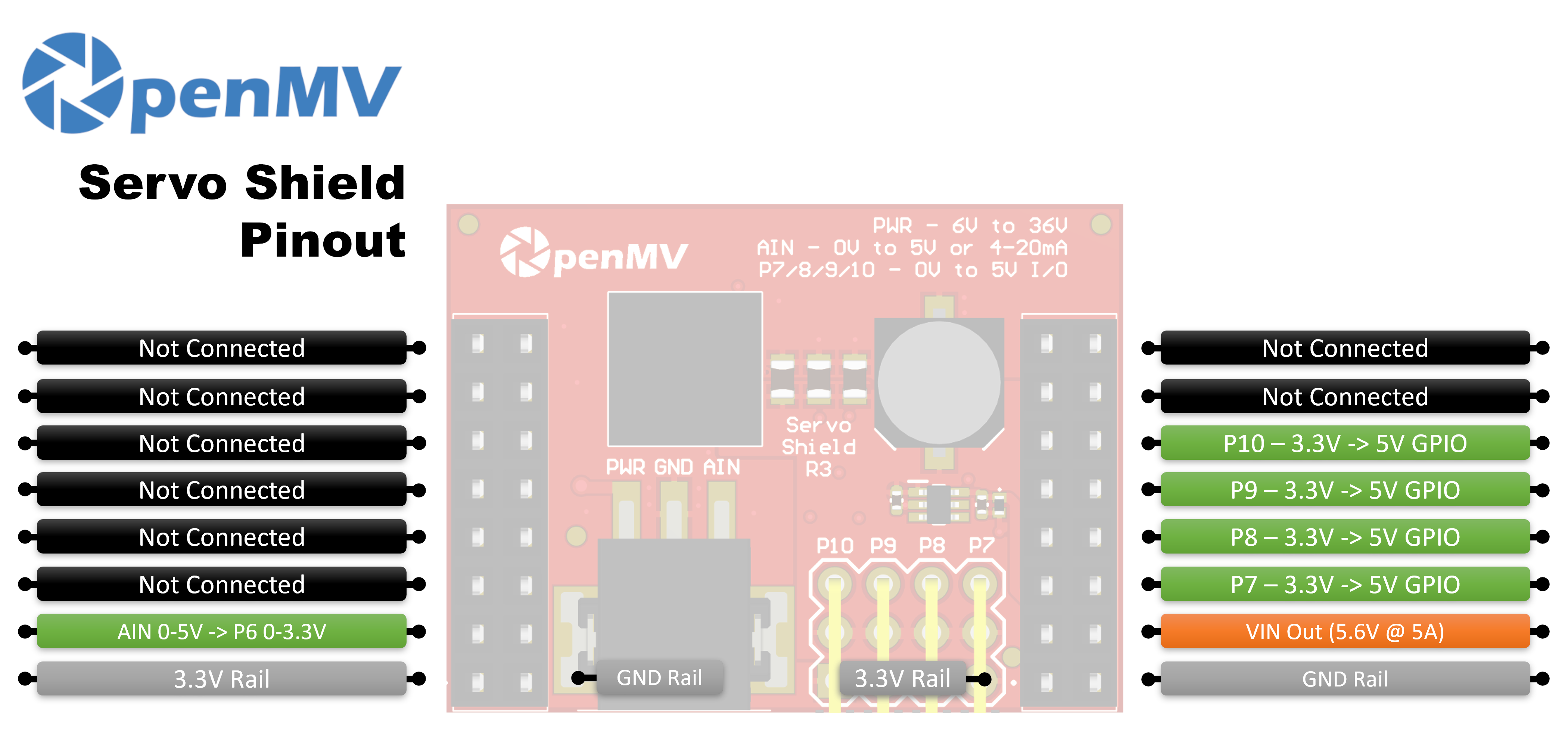
Pin reference
Pin |
Function |
|---|---|
P6 |
Level-shifted AIN readback (0–3.3 V on P6) |
P7 |
Servo 1 — bidirectional 3.3 V ↔ 5 V GPIO |
P8 |
Servo 2 — bidirectional 3.3 V ↔ 5 V GPIO |
P9 |
Servo 3 — bidirectional 3.3 V ↔ 5 V GPIO |
P10 |
Servo 4 — bidirectional 3.3 V ↔ 5 V GPIO |
PWR in |
6–36 V wide input on the terminal block (reverse-voltage tolerant) |
AIN in |
Analog input on the terminal block |
VIN out |
5.6 V regulated, up to 5 A combined for servos and camera |
3.3V rail |
Powers the shield’s on-board electronics |
GND rail |
Common ground |
Note
AIN is overvoltage-protected up to ±36 V and defaults to a 0–5 V voltage input, scaled down to 0–3.3 V on P6. Bridge the 4–20 mA mode shunt on the back of the shield to switch AIN to a 4–20 mA current-loop input.
Note
Each of P6–P10 is tied to the camera through a 0-ohm resistor on the back of the shield. Remove the resistor on any pin you want to reclaim for unrelated use.
Note
On the v2 version of the shield, P6–P9 are unidirectional 3.3 V → 5 V level shifters (output only). P10 is an open-drain digital line, pulled up to 3.3 V on the camera side and 5 V on the servo-pin side. By default it’s an input — the shield level-shifts 0–5 V on the servo pin down to 0–3.3 V on P10. Change the on-board solder jumper to flip P10 into an output, level-shifting 0–3.3 V on P10 up to 0–5 V on the servo pin.
Usage
Drive a hobby servo from any of P7–P10 with a 50 Hz PWM signal. The
pulse-width range varies between servos, so tune MIN_US and
MAX_US to match yours — typical values are around 1000–2000 µs:
from machine import Pin, PWM
import time

MIN_US = 1000  # full-left pulse width (microseconds)
MAX_US = 2000  # full-right pulse width

servo = PWM(Pin("P7"), freq=50)

def angle(deg):
    pulse_us = MIN_US + (deg * (MAX_US - MIN_US)) // 180
    servo.duty_ns(pulse_us * 1000)

while True:
    angle(0)
    time.sleep(1)
    angle(90)
    time.sleep(1)
    angle(180)
    time.sleep(1)
Read the AIN terminal-block input (the level-shifted result appears on P6):
from machine import ADC
import time

ain = ADC("P6")

while True:
    # 0–5 V on the AIN terminal scaled to 0–3.3 V on P6
    v = ain.read_u16() * 3.3 / 65535
    print("AIN:", v * (5.0 / 3.3), "V")
    time.sleep_ms(100)